System and method for enhanced electrostatic deposition and surface coatings

a technology of electrostatic deposition and surface coating, applied in the field of surface coating, can solve the problems of poor collection efficiency, poor coating densities, and poor nanoparticle generation and electrostatic collection (deposition) processes that produce surface coatings, and achieve the effect of enhancing the charge differential

Active Publication Date: 2014-08-05
MICELL MEDTECH INC +1
View PDF388 Cites 31 Cited by
  • Summary
  • Abstract
  • Description
  • Claims
  • Application Information

AI Technical Summary

Benefits of technology

[0003]Provided herein is a system for electrostatic deposition of particles upon a charged substrate to form a coating on a surface of the substrate, the system comprising: an expansion nozzle that releases coating particles having a first average electric potential suspended in a gaseous phase from a near-critical or supercritical fluid that is expanded through said nozzle; and an auxiliary emitter that generates a stream of charged ions having a second average potential in an inert carrier gas; whereby said coating particles interact with the charged ions and the carrier gas to enhance a charge differential between the coating particles and the substrate.
[0004]Provided herein is a system for electrostatic deposition of particles upon a charged substrate to form a coating on a surface of the substrate, the system comprising: an expansion nozzle that releases coating particles having a first average electric potential suspended in a gaseous phase from a near-critical or supercritical fluid that is expanded through the nozzle; and an auxiliary emitter that generates a stream of charged ions having a second average electric potential in an inert carrier gas; whereby the coating particles interact with the charged ions and the carrier gas to enhance a potential differential between the coating particles and the substrate.
[0005]In some embodiments, the coating particles have a first velocity upon release of the coating particles from the expansion nozzle that is less than a second velocity of the coating particles when the coating particles impact the substrate. In some embodiments, attraction of the coating particles to the substrate is increased as compared to attraction of the coating particles to the substrate in a system without the auxiliary emitter.

Problems solved by technology

Nanoparticle generation and electrostatic collection (deposition) processes that produce surface coatings can suffer from poor collection efficiencies and poor coating densities that result from inefficient packing of nanoparticles.

Method used


Image

  • System and method for enhanced electrostatic deposition and surface coatings
  • System and method for enhanced electrostatic deposition and surface coatings
  • System and method for enhanced electrostatic deposition and surface coatings

Examples


example 1

Coating Tests

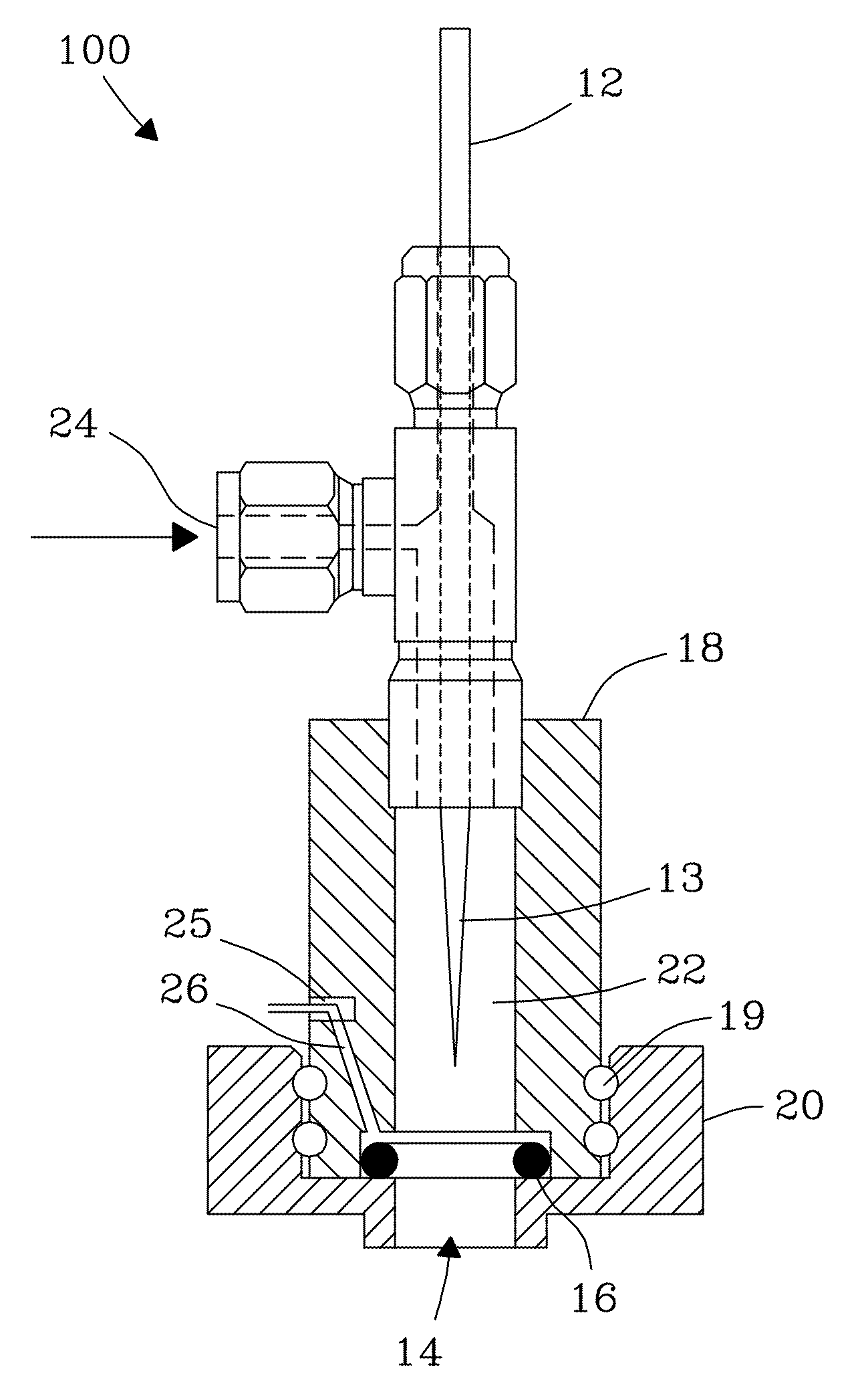
[0153]Coating efficiency tests were conducted in a deposition vessel (e.g., 8-liter glass bell jar) centered over a base platform equipped with an auxiliary emitter and e-RESS expansion nozzle assembly. The invention auxiliary emitter was positioned at the top of, and external to, the deposition vessel. The auxiliary emitter was configured with a 1st auxiliary electrode consisting of a central stainless steel rod (⅛-inch diameter) having a tapered tip that was grounded, and a ring collector (⅛-inch copper) as a 2nd auxiliary electrode. Charged ions from the auxiliary emitter were carried in (e.g., N2) carrier gas into the deposition vessel. An exemplary flow rate of pure carrier gas (e.g., N2) through the auxiliary emitter was 4.5 L / min. The auxiliary emitter was operated at an exemplary current of 1 μA under current / feedback control. The e-RESS expansion nozzle assembly included a metal sheath, as a first e-RESS electrode composed of a length (˜4 inches) of stainless s...

example 2

Coatings Deposited Absent the Auxiliary Emitter

[0155]A test was performed as in Example 1 without use of the auxiliary emitter. Weight gains from deposited coatings for each of three stents were: 22 μg, 40 μg, and 42 μg, respectively. Coating efficiency for the test was 5.0%. Results showed coatings on the stents were light, non-uniform, and dendritic. Coatings were heaviest at the upper end of the stents and had a dendricity rating of ˜7, on average. Heavier coatings were observed near the top of the stents. Lighter coatings were observed at the mid-to-lower end of the stents, with some amount of the metal stent clearly visible through the coatings.

example 3

Effect of Increasing Emitter Current on Deposited Polymer Weight / Structure

[0156]A dramatic effect is observed in weight gains for applied coatings at the initial onset of auxiliary emitter current. A gradual increase in weight gains occurs with increasing current between about 0.1 μA and 1 μA. Thereafter, a gradual decrease in weight gains occurs with change in auxiliary emitter current between about 1 μA and 5 μA, most likely due to a saturation of charge transferred to particles by the auxiliary emitter.


PUM

PropertyMeasurementUnit
sizeaaaaaaaaaa
sizeaaaaaaaaaa
velocityaaaaaaaaaa

Abstract

This disclosure describes the application of a supplemental corona source to provide surface charge on submicrometer particles to enhance collection efficiency and micro-structural density during electrostatic collection.

Description

FIELD OF THE INVENTION[0001]The present invention relates generally to surface coatings and processes for making. More particularly, the invention relates to a system and method for enhancing charge of coating particles produced by rapid expansion of near-critical and supercritical solutions that improves quality of surface coatings.BACKGROUND OF THE INVENTION[0002]A high coating density is desirable for production of continuous thin films on surfaces of finished devices following post-deposition processing steps. Nanoparticle generation and electrostatic collection (deposition) processes that produce surface coatings can suffer from poor collection efficiencies and poor coating densities that result from inefficient packing of nanoparticles. Low-density coatings are attributed to the dendritic nature of the coating. “Dendricity” as the term is used herein is a qualitative measure of the extent of particle accumulations or fibers found on, the coating. For example, a high dendricity...

Claims


Application Information

Patent Timeline
Patent Type & Authority Patents(United States)
IPC IPC(8): A61F2/06B05D1/04B05D7/14
CPCB05D1/04Y10T428/31938B05D1/025Y10T428/31786Y10T428/31504Y10T428/31507Y10T428/31663Y10T428/31544Y10T428/31935Y10T428/31551Y10T428/31855Y10T428/31931Y10T428/24372Y10T428/31725B05B5/032Y10T428/31511Y10T428/25B05D3/0486
Inventor FULTON, JOHN L.DEVERMAN, GEORGE S.MATSON, DEAN W.YONKER, CLEMENT R.TAYLOR, C. DOUGLASMCCLAIN, JAMES B.CROWLEY, JOSEPH M.
Owner MICELL MEDTECH INC
Why Eureka
Try Eureka