Fuel cell system and vehicle equipped with the same

a fuel cell and system technology, applied in the direction of battery/fuel cell control arrangement, electrochemical generators, battery/cell propulsion, etc., can solve the problems of etc., to avoid oxidation reduction electric potential, low system efficiency of the fuel cell system, and large switching loss of dc/dc converter

Active Publication Date: 2014-08-05
HONDA MOTOR CO LTD
View PDF29 Cites 2 Cited by
  • Summary
  • Abstract
  • Description
  • Claims
  • Application Information

AI Technical Summary

Benefits of technology

[0008]However, in the technique according to JP 2007-005038 A, in order to continuously avoid the oxidation reduction electric potential, chopping operation of the DC / DC converter occurs frequently, and the switching loss of the DC / DC converter is large. Therefore, the system efficiency of the fuel cell system is low disadvantageously.
[0009]The present invention has been made taking the problem of this type into account, and an object of the present invention is to provide a fuel cell system and a vehicle equipped with the fuel cell system which make it possible to prevent degradation of a fuel cell, and improve the system efficiency of the fuel cell system.
[0011]In the present invention, in the case where the output voltage of the energy storage device is outside a voltage range of the fuel cell where oxidation-reduction proceeds, the control unit controls the voltage regulator to be placed in the direct connection state (output voltage of the energy storage device≈output voltage of the fuel cell), not in a voltage step-up / step-down state where a voltage step-up / step-down operation is performed, and controls the gas supply unit so as to regulate concentration of the oxygen or the hydrogen supplied to the fuel cell in accordance with a target electric power for the power generation determined based on the electric power required by the load. Therefore, degradation of the fuel cell is prevented, and power loss related to the voltage step-up / step-down operation of the voltage regulator is reduced.
[0015]Further, preferably, the fuel cell system includes an outside temperature sensor for measuring an outside temperature, and if the outside temperature measured by the outside temperature sensor is a threshold temperature or more, the control unit controls the voltage regulator to be placed in the direct connection state, i.e., the energy storage device and the fuel cell are controlled to be placed in the direct connection state, at a voltage within the voltage range where reduction of the catalyst proceeds stably. If the outside temperature is lower than the threshold temperature, energy may be required, e.g., for warming up the fuel cell system at the time of restarting operation of the fuel cell system. In this case, the voltage of the energy storage device is kept high without implementing the direct connection control. In this manner, sufficient electric power can be secured.
[0017]Further, at the time of controlling the voltage regulator to be placed in the direct connection state, the control unit controls the target SOC value of the energy storage device to a threshold SOC value or less. The threshold SOC value corresponds to the lower limit voltage of the voltage range of the fuel cell where oxidation-reduction proceeds. In this manner, it is possible to place the energy storage device and the fuel cell in the direct connection state more frequently.
[0019]In the present invention, in the case where the output voltage of the energy storage device is outside a voltage range of the fuel cell where oxidation-reduction proceeds, the control unit controls the voltage regulator to be placed in the direct connection state, and controls the gas supply unit so as to regulate concentration of the oxygen or the hydrogen supplied to the fuel cell in accordance with a target power generation electric power determined based on electric power required by the load. Thus, it becomes possible to suppress degradation of the fuel cell, and improve the system efficiency of the fuel cell system.

Problems solved by technology

In this case, with excessive electric power generated in the fuel cell, a battery (energy storage device) is charged by stepping down the voltage through chopping operation of a DC / DC converter.
However, in the technique according to JP 2007-005038 A, in order to continuously avoid the oxidation reduction electric potential, chopping operation of the DC / DC converter occurs frequently, and the switching loss of the DC / DC converter is large.
Therefore, the system efficiency of the fuel cell system is low disadvantageously.

Method used


Image

  • Fuel cell system and vehicle equipped with the same
  • Fuel cell system and vehicle equipped with the same
  • Fuel cell system and vehicle equipped with the same

Examples


first embodiment

[First Embodiment]

[0143]In the above basic control, for example, in the case where the system load (system request load) Psys is high, the mode A control according to the normal I-V characteristic 162 at the voltage v2 (=0.8 V) or less in FIG. 13, related to the process of step S22 (FIG. 12) is implemented. That is, under the mode A control, the target FC voltage Vfctgt is variable, the cathode stoichiometric ratio (which is nearly equal to oxygen concentration) is normal, and the FC current Ifc is variable.

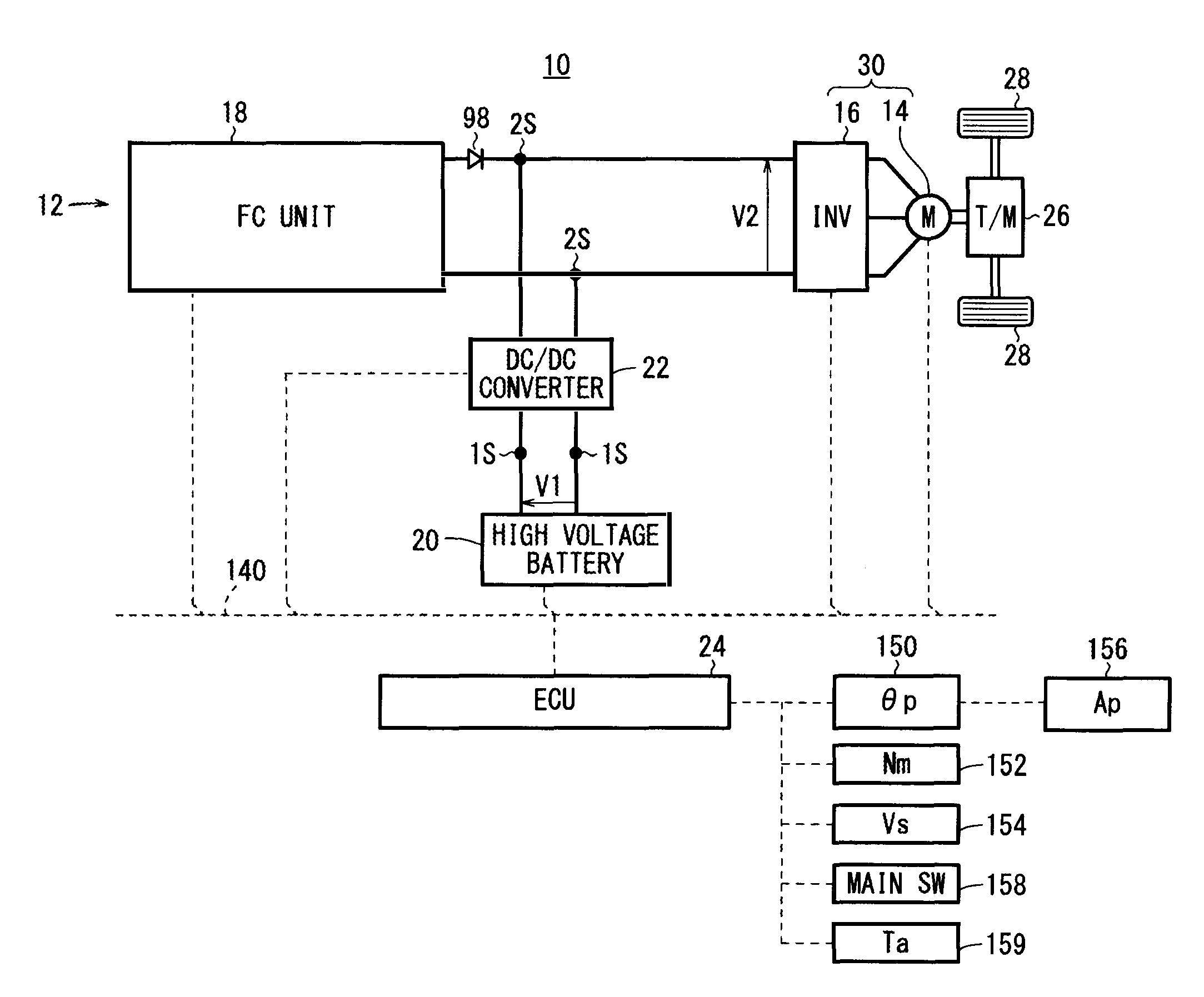
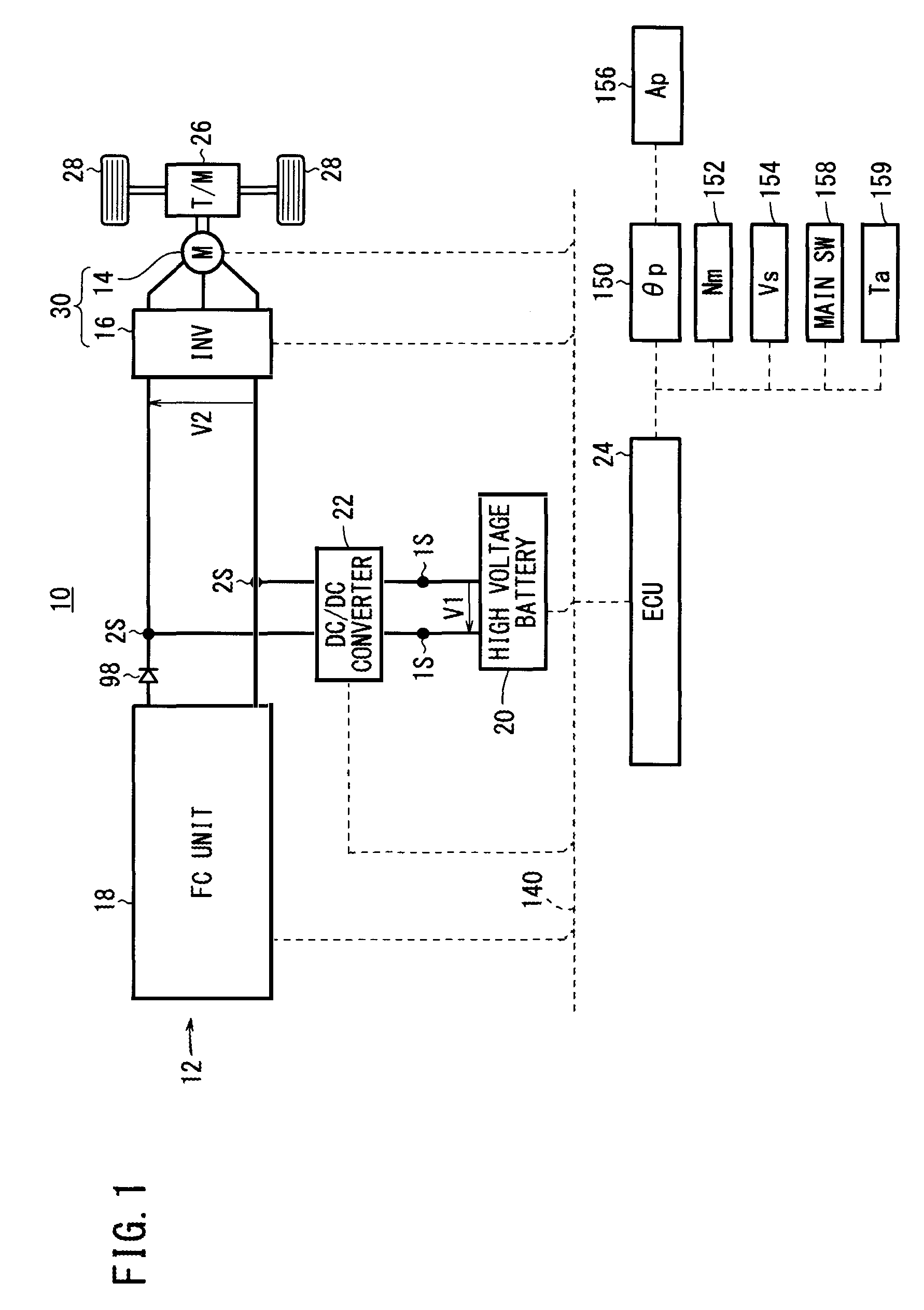
[0144]In this mode A control, the FC voltage Vfc is set by stepping up the primary voltage V1, i.e., the voltage Vbat of the battery 20, by the DC / DC converter 22 in FIG. 4.

[0145]Thus, in the mode A control implemented in the case where the system load (system request load) Psys is high, a switching loss occurs due to the voltage step-up switching (chopping) of the DC / DC converter 22.

[0146]More specifically, during the power supply mode for supplying electric power to the load 33...

second embodiment

[Second Embodiment]

[0165]FIG. 22 is a diagram schematically showing a structure of the FC unit 18 according to the second embodiment. In the FC unit 18 according to the second embodiment, in the cathode system 56a, a circulation valve (cathode circulation valve) 66 is included in addition to the air pump 60, the humidifier 62, and the back pressure valve 64.

[0166]In this case, the pipe 66a, the circulation valve 66, and the pipe 66b are connected between the pipe 64b on the output side of the back pressure valve 64 and the pipe 60a on the air intake side (input side). Thus, some of the exhaust gas (cathode off gas) is supplied as a circulating gas to the pipe 60a through the pipe 66a, the circulation valve 66, and the pipe 66b. The exhaust gas is mixed with the fresh air from the outside of the vehicle, and sucked into the air pump 60.

[0167]For example, the circulation valve 66 is a butterfly valve, and the opening degree of the butterfly valve (hereinafter referred to as the “circu...

third embodiment

[Third Embodiment]

[0171]In the direct connection control according to the first embodiment and the second embodiment as described above, at the time of starting the direct connection control, if the SOC value of the battery 20 is high, and the battery voltage Vat is kept to have a high value, it is highly probable that the battery voltage Vbat is within the oxidation reduction progress region R3.

[0172]If direct connection is implemented when the battery voltage Vbat is within the oxidation reduction progress region R3, the FC stack 40 is degraded. Therefore, if the SOC value of the battery 20 is high, practically, direct connection should not be performed. However, if direct connection is prohibited, the DC / DC converter 22 has to be operated. That is, the converter loss is increased and the efficiency in the vehicle is lowered. In an attempt to address the problem, the third embodiment offers a structure for increasing the frequency of implementing the direct connection control as m...


PUM

PropertyMeasurementUnit
voltageaaaaaaaaaa
voltage v2aaaaaaaaaa
voltage v3aaaaaaaaaa

Abstract

A fuel cell system and a fuel cell vehicle equipped with the fuel cell system are provided. In a case where the voltage of a battery is outside a voltage range of fuel cells where oxidation-reduction proceeds, an ECU controls a DC / DC converter to be placed in a direct connection state (Vbat≈Vfc), and controls a gas supply unit so as to regulate concentration of oxygen or hydrogen supplied to the fuel cells in accordance with a target power generation electric power determined based on electric power required by a load.

Description

CROSS-REFERENCE TO RELATED APPLICATION[0001]This application is based upon and claims the benefit of priority from Japanese Patent Application No. 2011-135905 filed on Jun. 20, 2011, of which the contents are incorporated herein by reference.BACKGROUND OF THE INVENTION[0002]1. Field of the Invention[0003]The present invention relates to a fuel cell system including a voltage regulator and an energy storage device which are connected in series to each other, a fuel cell connected in parallel to the serially connected voltage regulator and energy storage device, and a load driven by a combined power source of the energy storage device and the fuel cell. Further, the present invention relates to a vehicle equipped with such a fuel cell system. Such a fuel cell system and such a vehicle equipped with the fuel cell system make it possible to suppress degradation of the fuel cell, and improve the system efficiency.[0004]2. Description of the Related Art[0005]A fuel cell employs a membrane...

Claims


Application Information

Patent Timeline
Patent Type & Authority Patents(United States)
IPC IPC(8): H01M12/00
CPCB60L11/1861Y02T10/7044B60L2210/12H01M8/04298B60L1/003Y02T10/7233B60L11/1803B60L11/1887Y10T307/516Y02T10/7225Y02E60/50B60L2210/14H01M16/006Y02T10/7011Y02T10/7066H01M8/04798B60L11/1868Y02T90/34B60L50/51B60L58/12B60L58/20B60L58/40Y02E60/10Y02T10/70Y02T10/72Y02T90/40
Inventor KAZUNO, SHUICHISAEKI, HIBIKIWATANABE, KAZUNORI
Owner HONDA MOTOR CO LTD
Why Eureka
Try Eureka