Material absorbing electromagnetic waves

a technology of electromagnetic waves and materials, applied in the field of metals, can solve the problems of reducing the efficiency of electromagnetic waves, affecting the application of electromagnetic waves, and affecting the effect of electromagnetic waves, and achieve the effect of great ease in its implementation and us

Active Publication Date: 2014-08-12
DELPECH MARC +1
View PDF9 Cites 6 Cited by
  • Summary
  • Abstract
  • Description
  • Claims
  • Application Information

AI Technical Summary

Benefits of technology

[0019]The present invention aims at allowing the manufacturing of a thin material absorbing electromagnetic waves having great ease in its implementation and use.
[0021]Thus, by printing the conducting layer and absorbing patterns directly on a textile layer, it is possible to obtain a not very thick, flexible, relatively simple material and fast to manufacture and adapt, the desired absorbing patterns may easily be printed directly.
[0022]Advantageously, the conductive ink is an ink based on carbon black. More particularly it may be an aqueous ink based on carbon nanoparticles, preferentially with a size of about 300 angstroms. With such an ink, it is possible to obtain relatively high conductivity with a low printing load on the textile.
[0029]According to a preferred embodiment, the printed textile is a non-woven textile. Advantageously, this is a microfiber textile, advantageously with polymer fibers, notably imparting strength, long lastingness, toughness and durability.
[0031]Advantageously, the material comprises a plurality of printed layers, notably according to patterns different from each other. The application of several printed layers allows absorption of a wider range of frequencies and may notably give the possibility of letting through frequencies belonging to a given range of frequencies. The multilayer configuration also gives the possibility of making the material not very sensitive or even insensitive to the direction of polarization of the received waves.

Problems solved by technology

This for example is the case of wind turbines which, because of their rotating vanes may generate parasitic signals on meteorological or air control radar screens.
A drawback: the quarter wave material operates well for a single specific wave length and its efficiency decreases all the more so since the incident wave length is far from this ideal length.Materials absorbing the incident wave by energy conversion: the material transforms the radar waves into infrared waves, so that there is no reflected wave.
All these materials are often heavy, and / or thick, and / or brittle, and / or limited to a relatively narrow frequency range.
The application of a honeycomb structure makes the material particularly brittle and relatively not very adaptable to any type of surface, notably to curved surfaces.
Such a material is therefore not very adaptable and particularly complex to apply.
The application of such a material therefore remains relatively complex.

Method used


Image

  • Material absorbing electromagnetic waves
  • Material absorbing electromagnetic waves
  • Material absorbing electromagnetic waves

Examples


Embodiment Construction

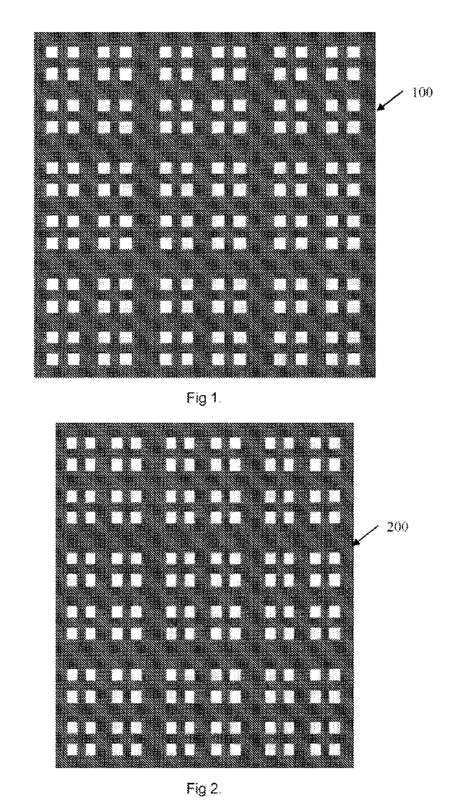
[0048]FIG. 1 shows a material 100 according to the invention comprising a printed textile layer, notably by screen printing, by means of at least one conductive ink, preferentially an aqueous ink, based on carbon particles of about 300 angstroms.

[0049]The textile layer used is a non-woven textile marketed under the name of Sontara® by Dupont de Nemours having a thickness of 0.22 mm.

[0050]The textile layer comprises printed areas and non-printed areas; these are non-printed areas appearing as substantially rectangular two-dimensional periodic patches.

[0051]More specifically, the patterns of the textile layer are in this case obtained by intersected printing of lines with determined thicknesses, spaced apart, and oriented perpendicularly.

[0052]Thus, the pattern illustrated in FIG. 1 results from the repeated printing of a thick line (with a thickness e), of a thin line (thickness e / 4), of a medium line (thickness e / 2), and of a new thin line, each line being spaced apart from its neig...


PUM

PropertyMeasurementUnit
sizeaaaaaaaaaa
thicknessaaaaaaaaaa
thicknessaaaaaaaaaa

Abstract

The invention relates to a material that absorbs electromagnetic waves, characterized in that it includes at least one textile layer printed using at least one conductive ink in accordance with at least one pattern including printed areas and non-printed areas in an arrangement suitable for a corresponding range of absorption frequencies.

Description

TECHNICAL FIELD[0001]The invention relates to a metamaterial for applying an absorbent screen towards electromagnetic radiation, notably in the field of ultra high frequencies, super high frequencies and extremely high frequencies.BRIEF DESCRIPTION OF RELATED ART[0002]The increasingly frequent use of appliances emitting electromagnetic waves in many fields of applications, and notably, i.e., in the fields of telecommunications, aviation, health care, makes the capability increasingly significant of being able to isolate certain objects selectively from undesired electromagnetic radiations propagating in their environment.[0003]For example, it may be desirable to efficiently isolate certain portions of the body of a patient from electromagnetic radiation emitted by a scanner appliance for example, so that only the targeted area of the body is exposed to electromagnetic radiation. This for example is the case of patients having undergone surgical operations following which, metal elem...

Claims


Application Information

Patent Timeline
Patent Type & Authority Patents(United States)
IPC IPC(8): G21F1/12H01B1/22
CPCH01Q17/002G21F1/12F05B2260/99
Inventor DELPECH, MARCLHOMME, CHRISTIAN
Owner DELPECH MARC
Why Eureka
Try Eureka