
Staged blowdown of adsorbent bed

a technology of adsorption bed and adsorption bed, which is applied in the direction of separation process, dispersed particle separation, chemistry apparatus and processes, etc., can solve the problems of increasing the number of valves required, increasing the degree of complexity, and increasing the performance, so as to improve the system performance and monitoring, and simplify the process. , the effect of increasing the degr

Inactive Publication Date: 2014-09-09
LUMMUS TECH INC
View PDF11 Cites 0 Cited by
  • Summary
  • Abstract
  • Description
  • Claims
  • Application Information

AI Technical Summary

Benefits of technology

The patent describes a way to improve the performance and monitoring of a gas purification process using multiple valves. By opening these valves sequentially, the system can better control the flow of gases and increase the productivity of the adsorbent. The use of valves also allows for easier verification of their operation, and the resulting system has a simpler design and reduced risk of malfunction.

Problems solved by technology

Unfortunately, the increases in performance were accompanied by an increase in the number of valves required from thirty-one for the Wagner process to thirty-three for the Batta process to a minimum of forty-four for the Fuderer et al. process.
Although these methods facilitate excellent product recovery and adsorbent productivity, they do so at the expense of a high degree of complexity.
Although these cycles progressed in the critical areas of recovery and productivity, they did so at the expense of much increased mechanical complexity.
This increase in complexity is accompanied by increases in system volume, mass, assembly time, and capital cost.
Furthermore, the large increase in the number of valves over time significantly reduces the reliability of the PSA system; as such PSA systems are single point of failure systems, which must be shut down even if one valve fails.
It has been found that in the limit of extremely-rapid cyclic operation, that the flowrate achieved through the invention of Lomax '895 may undesirably limit the rapidity with which a pressure equalization step can be executed, thus limiting adsorbent productivity.

Method used


Image

  • Staged blowdown of adsorbent bed
  • Staged blowdown of adsorbent bed
  • Staged blowdown of adsorbent bed

Examples


Embodiment Construction

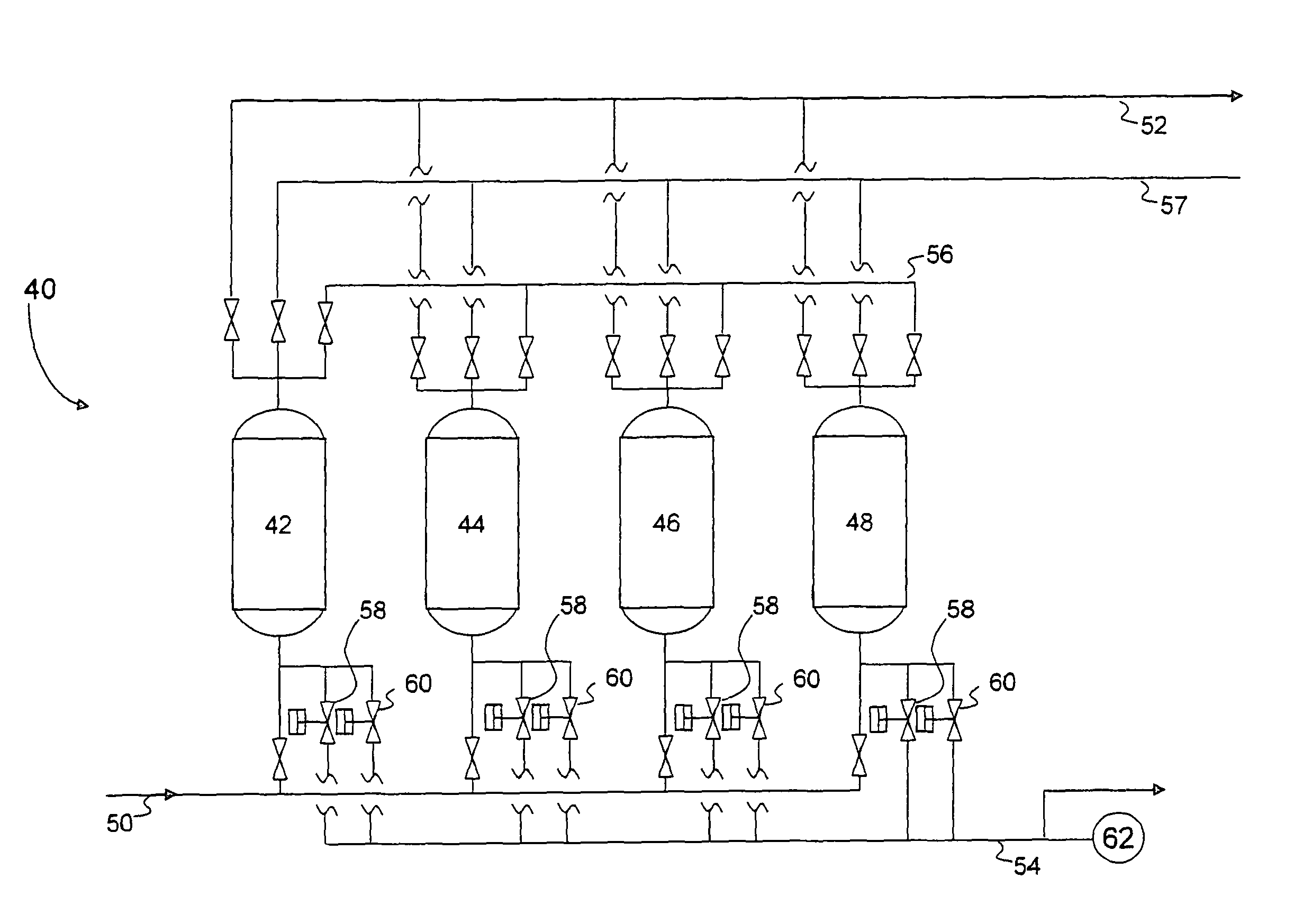
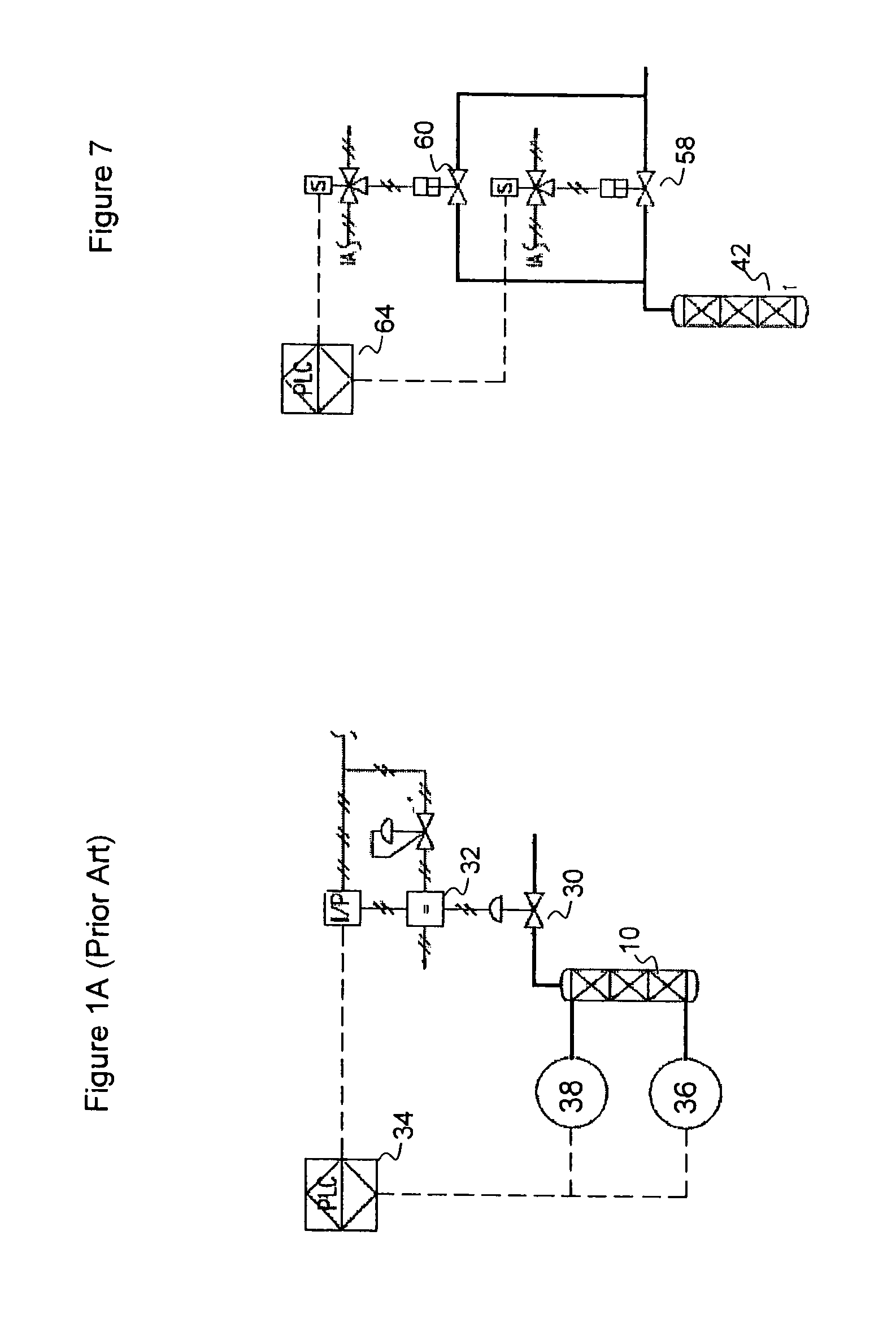
[0037]In one aspect, embodiments disclosed herein relate to methods and apparatus for controlling the flow of gases entering or exiting a bed of adsorbent. More specifically, embodiments disclosed herein relate to the use of two or more valves for controlling the flow of gases entering or exiting a bed of adsorbents, where the two valves are opened sequentially (i.e., in at least two actions separated by a delay in time).

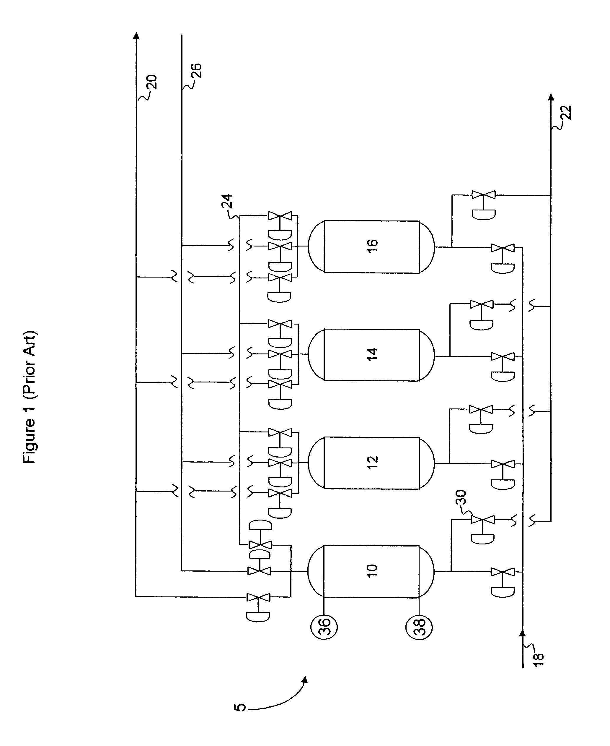
[0038]Referring now to FIG. 1, a simplified process flow diagram of a prior art PSA system is illustrated. The PSA system 5 includes a first vessel 10, a second vessel 12, a third vessel 14, and a fourth vessel 16. Each of the vessels 10, 12, 14, 16 typically includes one or more beds of adsorbent material. The vessels 10, 12, 14, 16 are connected in parallel flow relation between a source manifold 18, which supplies a feed gas mixture, and a product manifold 20, which provide an outlet for unabsorbed product effluent gas. The vessels 10, 12, 14, 16 are also connect...


PUM

PropertyMeasurementUnit
pressure lossaaaaaaaaaa
pressureaaaaaaaaaa
diameteraaaaaaaaaa

Abstract

A pressure swing adsorption (PSA) system using two or more valves for controlling the flow of gases entering or exiting a bed of adsorbents is disclosed, where the two or more valves are opened sequentially (i.e., in at least two actions separated by a delay in time). The sequential opening of the valves may increase the degree to which adsorbed species are purged from the bed, and also facilitates more rapid execution of certain time steps of the PSA cycle, thus increasing adsorbent productivity The sequential opening of the valves may also allow for verification of valve operation by measuring either the absolute value, the slope (derivative) or the rate of change of derivative of the pressure, either in the adsorbent bed, in the downstream manifold, or in a volume of gas held in a buffer vessel.

Description

CROSS-REFERENCE TO RELATED APPLICATIONS[0001]This is the national stage of International Application No. PCT / US2011 / 034253 filed Apr. 28, 2011, which claims priority from U.S. Provisional Patent Application Ser. No. 61 / 331,612 filed May 5, 2010.FIELD OF THE DISCLOSURE[0002]Embodiments disclosed herein generally relate to pressure swing adsorption systems. More specifically, embodiments disclosed herein relate to methods and apparatus for controlling the flow of gases entering or exiting a bed of adsorbent.BACKGROUND[0003]Pressure Swing Adsorption (PSA) is a technique used to fractionate mixtures of gases to provide at least one purified product gas and a raffinate byproduct mixture. PSA has been successfully used to separate hydrogen from other gases, oxygen and nitrogen from air, and helium from natural gas, among others.[0004]Early PSA systems generally used four adsorbent vessels operated in parallel. An example of this is U.S. Pat. No. 3,430,418 to Wagner. Later improvements to ...

Claims


Application Information

Patent Timeline
Patent Type & Authority Patents(United States)
IPC IPC(8): B01D53/053B01D53/047
CPCB01D53/047B01D2259/40011B01D53/053B01D2259/40003B01D2259/40009B01D2259/404B01D53/0446B01D53/30
Inventor LOMAX, FRANKLIN D.TODD, RICHARD S.ZAKRAJSEK, BRIAN A.
Owner LUMMUS TECH INC
Learn More