Ultrasonic probe

a technology of ultrasonic probes and electrode connectors, applied in ultrasonic/sonic/infrasonic image/data processing, mechanical vibration separation, application, etc., can solve the problems of irregular conductance resistance of electrode connectors, irregular sensitivities between arrays, and severer problems, so as to achieve good working properties and keep quality good

Active Publication Date: 2014-09-16
KONICA MINOLTA INC
View PDF22 Cites 0 Cited by
  • Summary
  • Abstract
  • Description
  • Claims
  • Application Information

AI Technical Summary

Benefits of technology

[0011]The present invention is proposed in order to solve the above-mentioned conventional problems and intended to provide an ultrasonic probe of a structure in which a quality is kept good, and the sensibility irregularity between arrays is small, and the working property is good.
[0021]With this configuration, electrical gaps between surfaces of respective layers are filled with the graphite powder so that the electrical connection can be reinforced, and the irregularities of the conduction resistances of the piezoelectric element, the conductive acoustic matching layer, the polymer film on which the conductive pattern is formed, and the electrical connector in the conductive pattern of the FPC, which are adhesively layered, are small which can reduce the sensibility irregularity between the arrays.
[0023]With this configuration, the graphite powder intrudes into the concave and convex portions on the surface of the piezoelectric element, and the adhesive property between the mutual materials, namely, the contact area between the mutual materials is increased, thereby decreasing the irregularity of the conduction resistance of the electric connector. As a result, the sensibility irregularity between the arrays is reduced. Also, since the concave depth of the piezoelectric element and the diameter of the graphite powder are equal in size, the mutual materials can be adhered in the very thinly manner. Thus, the absorption, reflection and dispersion losses of the ultrasonic waves, which are caused by the adhesive or the graphite powder inside the adhesive, are suppressed, which results in the improvement of the sensibility of the ultrasonic probe.
[0025]With this configuration, the difference of the acoustic impedance between the adhesive layer 1, the adhesive layer 2 and the conductive acoustic matching layer is decreased, and the difference of the acoustic impedance between the adhesive layer 3, the electrode of the second film, and the backing material is decreased. Thus, the reflection loss of the ultrasonic waves that are generated by the boundary surface between acoustic media is suppressed, which results in the improvement of the sensibility of the ultrasonic probe.
[0027]With this configuration, the acoustic impedance of the piezoelectric element is decreased, and the matching property with the living body organization is made better. As a result, the acoustic transmission loss is reduced, and the sensibility of the ultrasonic probe is improved.
[0028]The present invention can provide the ultrasonic waves in which, when the piezoelectric element, the conductive acoustic matching layer, the first film on which the electrode pattern is formed, and the second film where the electrode pattern is formed are layered and adhered, the thermosetting two-component type adhesive in which the graphite powder is uniformly distributed is used, thereby reducing the irregularity of the conduction resistance of the electric connector, and as a result, there is the effect of the reduction in the sensibility irregularity between the arrays.

Problems solved by technology

However, the conduction resistances of the electrode connectors are irregular in the respective arrays.
As a result, there was a problem that the sensitivities were irregular between the arrays.
A higher frequency orientation makes its problem severer, in recent years in which the width of the division electrode is narrower.
When the polarization-treated piezoelectric element is placed under the high temperature environment such as 100 deg C. or more, the piezoelectric property is lost, which causes the practical use of the conductive paste or anisotropic conductive adhesive from being prevented.
Also, the conductive paste and the anisotropic conductive adhesive have the problem that they are expensive.

Method used


Image

  • Ultrasonic probe
  • Ultrasonic probe
  • Ultrasonic probe

Examples


first embodiment

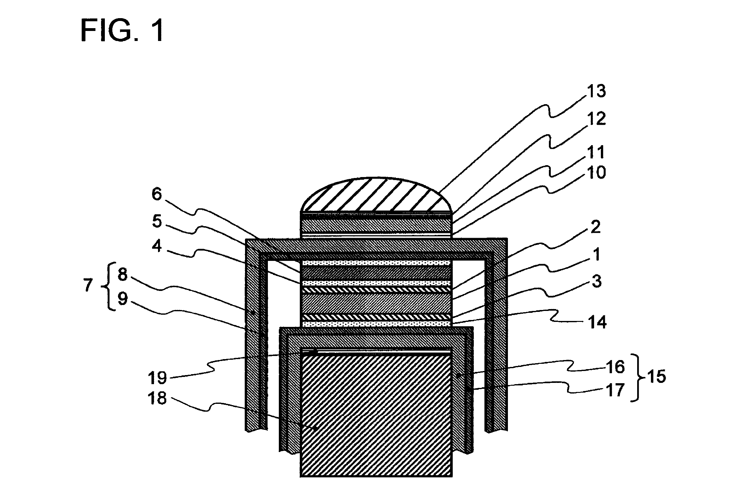
[0040]FIG. 1 shows the ultrasonic probe in the first embodiment according to the present invention. FIG. 1 is the sectional view in the short axis direction of the ultrasonic probe. By the way, in the explanation of this drawing, [UP] and [DOWN] are assumed to indicate the upward direction and the downward direction in the plane of the drawing paper, respectively (similarly also in FIGS. 4 and 6). In FIG. 1, a piezoelectric element 1 is a piezoelectric element in which a piezoelectric ceramics such as a PZT group and the like, a single crystal, and a polymer such as PVDF and the like are used. On one surface of each of a plurality of piezoelectric elements 1, a ground electrode layer 2 is formed as a first electrode layer, and on the other side, a positive electrode layer 3 is formed as a second electrode layer, respectively, in advance.

[0041]In this embodiment, the ground electrode layer 2 and the positive electrode layer 3 are assumed to be the gold sputter electrode layers whose ...

second embodiment

[0064]The ultrasonic probe of the second embodiment according to the present invention will be described below.

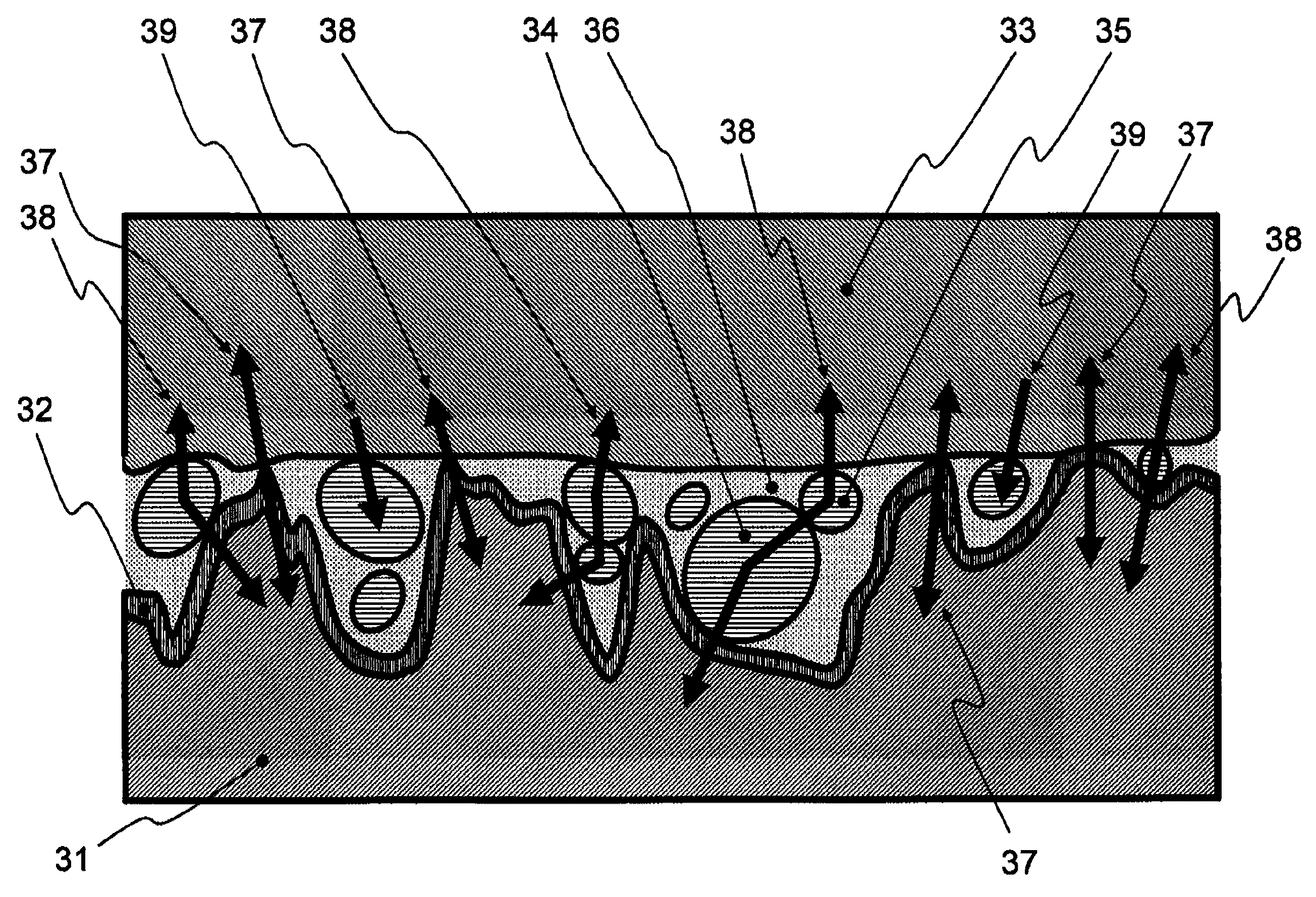
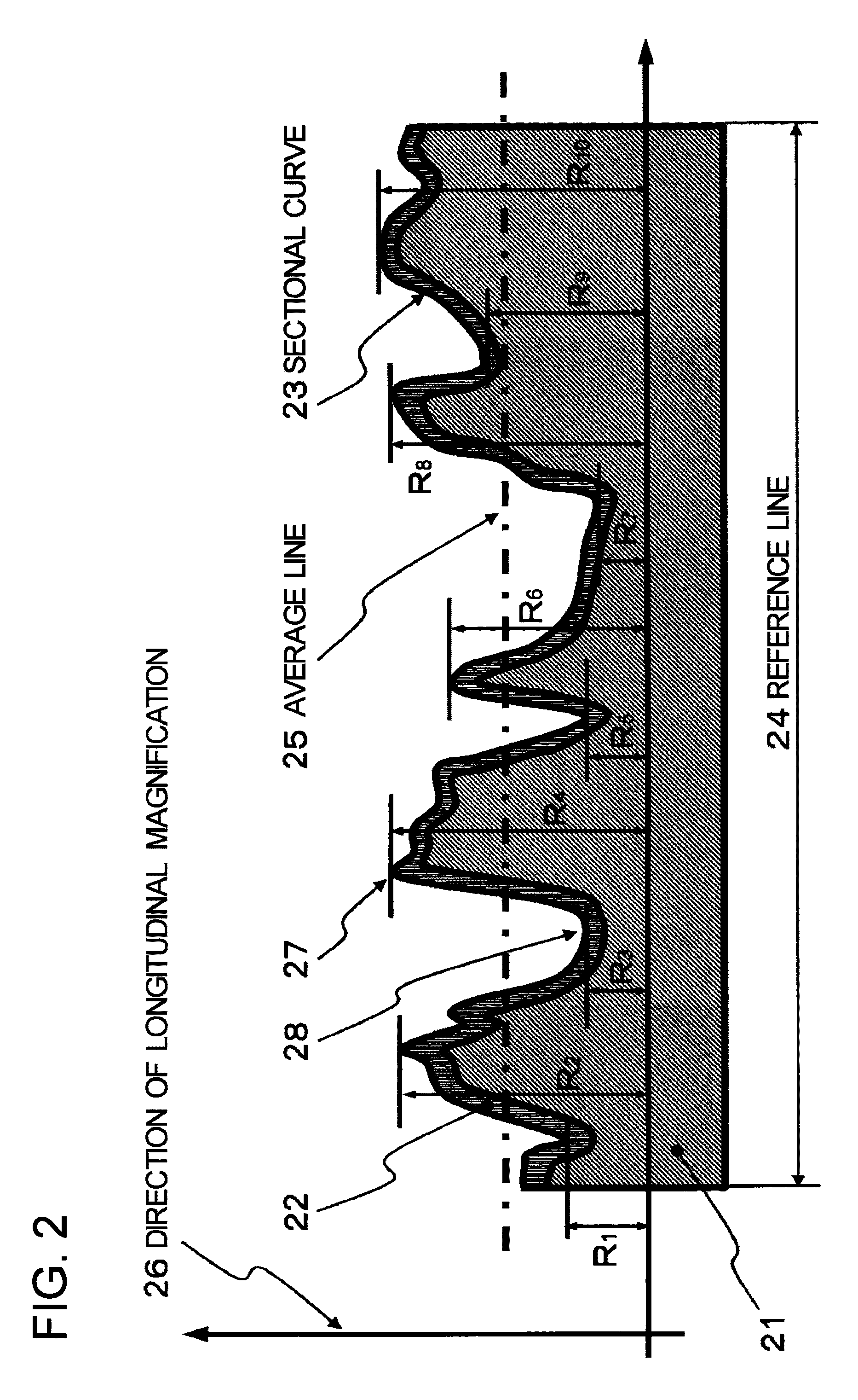
[0065]In the ultrasonic probe in the second embodiment, a 10-point average roughness (Rz) on the surfaces of the electrode layers formed on both the surfaces of the piezoelectric element 1 in the ultrasonic probe in the first embodiment is set to a range from 3.5 μm to 6.5 μm. Moreover, an average particle diameter between the graphite powder of the thermosetting two-component type adhesive layers 4, 6 and 14 in which the graphite powder is uniformly distributed to adhere the polymer film 7, the conductive acoustic matching layer 5, the piezoelectric element 1 and the FPC 15, respectively, is set to a range from 3.5 μm to 6.5 μm.

[0066]FIG. 2 shows the shape (the roughness) of the surface on the section of a piezoelectric element 21.

[0067]A ground electrode layer 22 is a layer that is formed on the surface of the piezoelectric element 21 by the gold sputtering (the positive ...

third embodiment

[0081]As mentioned above, according to the ultrasonic probe in the third embodiment according to the present invention, the graphite powder is uniformly distributed in: the adhesive layer 1 that is located between the first electrode layer formed on one side of the piezoelectric element and one or more conductive acoustic matching layers; and the adhesive layer 2 that is located between one or more conductive acoustic matching layers and the first film on which the electrode pattern is formed, and the tungsten powder is uniformly distributed in the adhesive layer 3 that is located between the second electrode layer formed on the other side of the piezoelectric element and the second film on which the electrode pattern is formed. Thus, the reflection loss of the ultrasonic waves generated on the boundary surface between the acoustic media is reduced, which results in the improvement of the sensibility of the ultrasonic probe.


PUM


Abstract

An ultrasonic probe that enables the sensibility irregularity between arrays to be reduced is disclosed. This piezoelectric element contains: a piezoelectric element 1; a first electrode layer 2 formed on one side of the piezoelectric element 1; one or more conductive acoustic matching layers 5 layered via an adhesive layer 4 on the first electrode layer 2; a first film 7 which is layered via an adhesive layer 6 on the acoustic matching layer 5 and in which an electrode pattern is formed on the side of the adhesive layer 6; a second electrode layer 3 formed on the other side of the piezoelectric element 1; and a second film 15 which is layered via an adhesive layer 14 on the second electrode layer 3 and in which an electrode pattern is formed on the side of the adhesive layer 14, wherein the adhesive layers 4, 6 and 14 are thermosetting two-component type adhesives in which graphite powder is uniformly distributed therein.

Description

TECHNICAL FIELD[0001]The present invention relates to an ultrasonic probe that is connected to an ultrasonic diagnostic apparatus, which can emit ultrasonic waves into the body of an examinee and display the picture of the inside of the body interior, from the ultrasonic waves reflected by a boundary between respective body elements.BACKGROUND ART[0002]The prior art of the present invention will be described below by using the drawings. FIG. 8 is a view showing the configuration of a conventional ultrasonic probe (for example, see the following patent document 1). In the explanation of this drawing, [UP] and [DOWN] are assumed to indicate the upward direction and the downward direction in the plane of the drawing paper, respectively. In FIG. 8, a piezoelectric element 81 having electrodes on both surfaces is an element for transmitting and receiving ultrasonic waves. On the upper surface of the piezoelectric element 81, a ground electrode layer 82 is formed as a first electrode laye...

Claims


Application Information

Patent Timeline
Patent Type & Authority Patents(United States)
IPC IPC(8): A61B8/14A61B8/00A61B8/08B06B1/06
CPCA61B8/08A61B8/463B06B1/0622A61B8/488
Inventor OOURA, KOUJIFUKASE, HIROKAZU
Owner KONICA MINOLTA INC
Why Eureka
Try Eureka