
Micro-extrusion printhead with offset orifices for generating gridlines on non-square substrates

a micro-extrusion and gridline technology, applied in the direction of sweetmeats, dough shaping, food shaping, etc., can solve the problems of reducing solar cell efficiency, and consuming a lot of silicon, so as to simplify the flow distribution system design, facilitate the adjustment of offset distance, and save time and cost

Active Publication Date: 2014-11-04
XEROX CORP
View PDF130 Cites 5 Cited by
  • Summary
  • Abstract
  • Description
  • Claims
  • Application Information

AI Technical Summary

Benefits of technology

This approach enables the production of H-pattern solar cells with minimal ink waste, no corner masking required, and no risk of printing beyond the wafer edge, while maintaining cell efficiency and allowing for substitution on existing machines with minimal effort, thus reducing manufacturing complexity and cost.

Problems solved by technology

However, poly-silicon wafers are characterized by an imperfect surface due to the multitude of crystal grain boundaries, which impedes the transmission of sunlight into the cell, which reduces solar energy absorption and results in lower solar cell efficiency (i.e., less electricity per unit area).
Note that forming these ‘pseudo’ square substrates involves cutting away peripheral sections of the circular wafer, which creates a substantial waste of silicon.
Screen-printing techniques were first used in the large scale production of solar cells, but has a drawback in that it requires physical contact with the semiconductor substrate, resulting in relatively low production yields.
Another problem faced by mono-crystalline-based solar cells is that current solar cell extrusion printing equipment that is optimized for poly-silicon-based solar cells cannot be used in an efficient manner to make octagonal (“pseudo-square”) mono-crystalline-based solar cells.
This approach would allow the use of currently available equipment, but would greatly increases manufacturing costs, would potentially reduce yields by requiring substantial pre-extrusion or post-extrusion processing of the octagonal mono-silicon wafers, and would also waste gridline material.
However, this approach would require significant (and very expensive) changes to the micro-extrusion control system, and would be difficult to implement due to the large number of valves that would be required.
Moreover, adding a large number of external valves to the existing co-extrusion system is problematic due to space limitations and payload on the existing micro-extrusion systems utilized to generate solar cells on square poly-silicon substrates.

Method used


Image

  • Micro-extrusion printhead with offset orifices for generating gridlines on non-square substrates
  • Micro-extrusion printhead with offset orifices for generating gridlines on non-square substrates
  • Micro-extrusion printhead with offset orifices for generating gridlines on non-square substrates

Examples


case 62c

[0080]Outer case 62C is a pressure container defining an inlet port 62C-IN through which gridline material is received at pressure P0 from gridline material source 60C-1 (as shown in FIG. 10) into a first inner chamber portion 63C-1, and an outlet port 62C-OUT that passes gridline material from a second inner chamber portion 63C-2 at one of desired inlet pressures P11, P21 or P31 to printhead 100C (no shown). Fixed seal structure 64C is fixedly disposed inside outer case 62C between first inner chamber portion 63C-1 and second inner chamber portion 63C-2, and includes a seal 64C-1 (e.g., an o-ring, gasket or cup-seal) that defines a central opening 64C-2.

[0081]Movable piston 65C includes a relatively small diameter shaft 66C, a relatively large diameter stopper 67C, and a conic surface 68C that tapers from the relatively large diameter of stopper 67C to the relatively small diameter of shaft 66C. A first portion of shaft 66C disposed outside outer case 62C is operably connected to a...


PUM

PropertyMeasurementUnit
acute angleaaaaaaaaaa
offset distanceaaaaaaaaaa
timeaaaaaaaaaa

Abstract

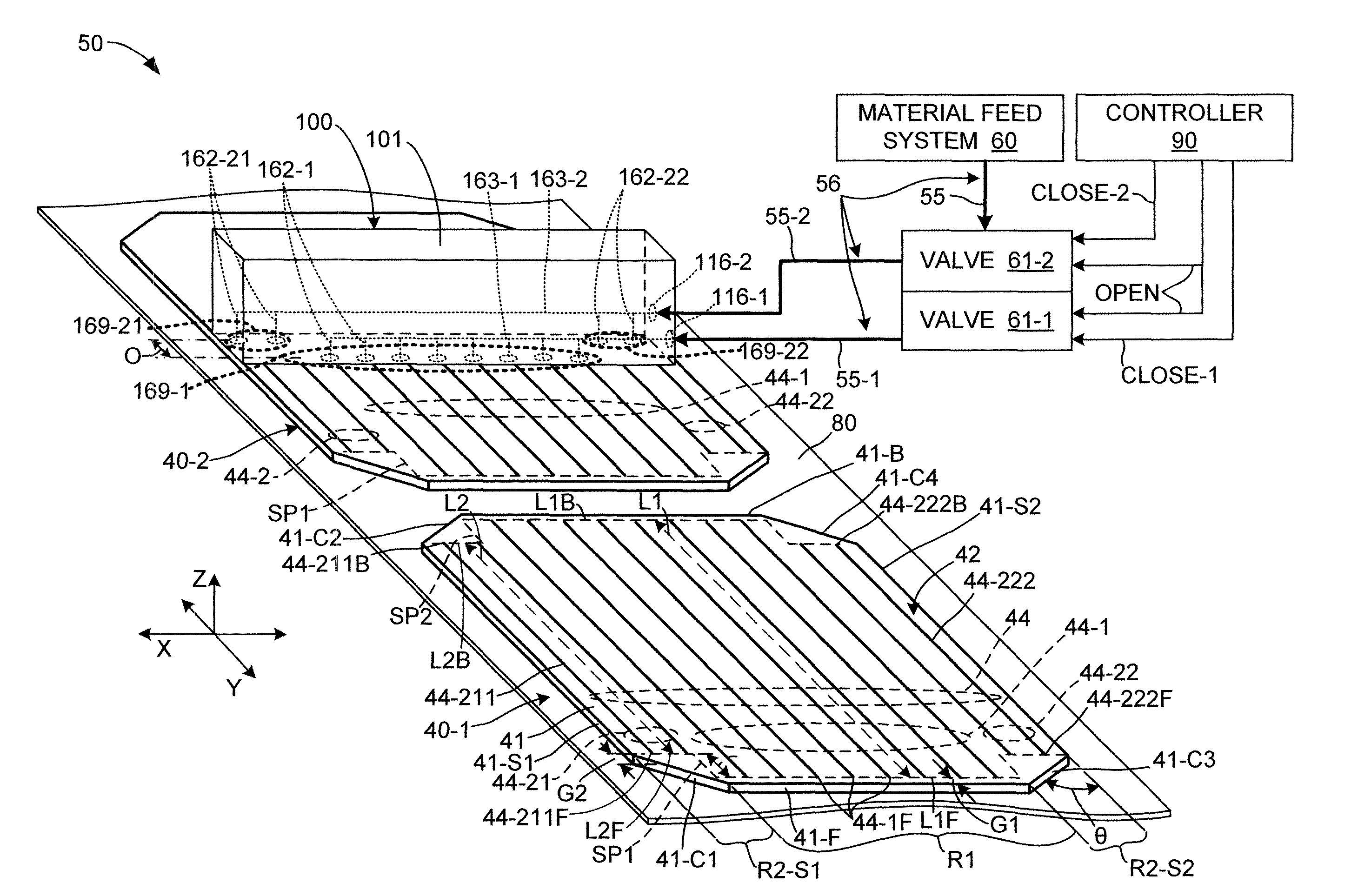
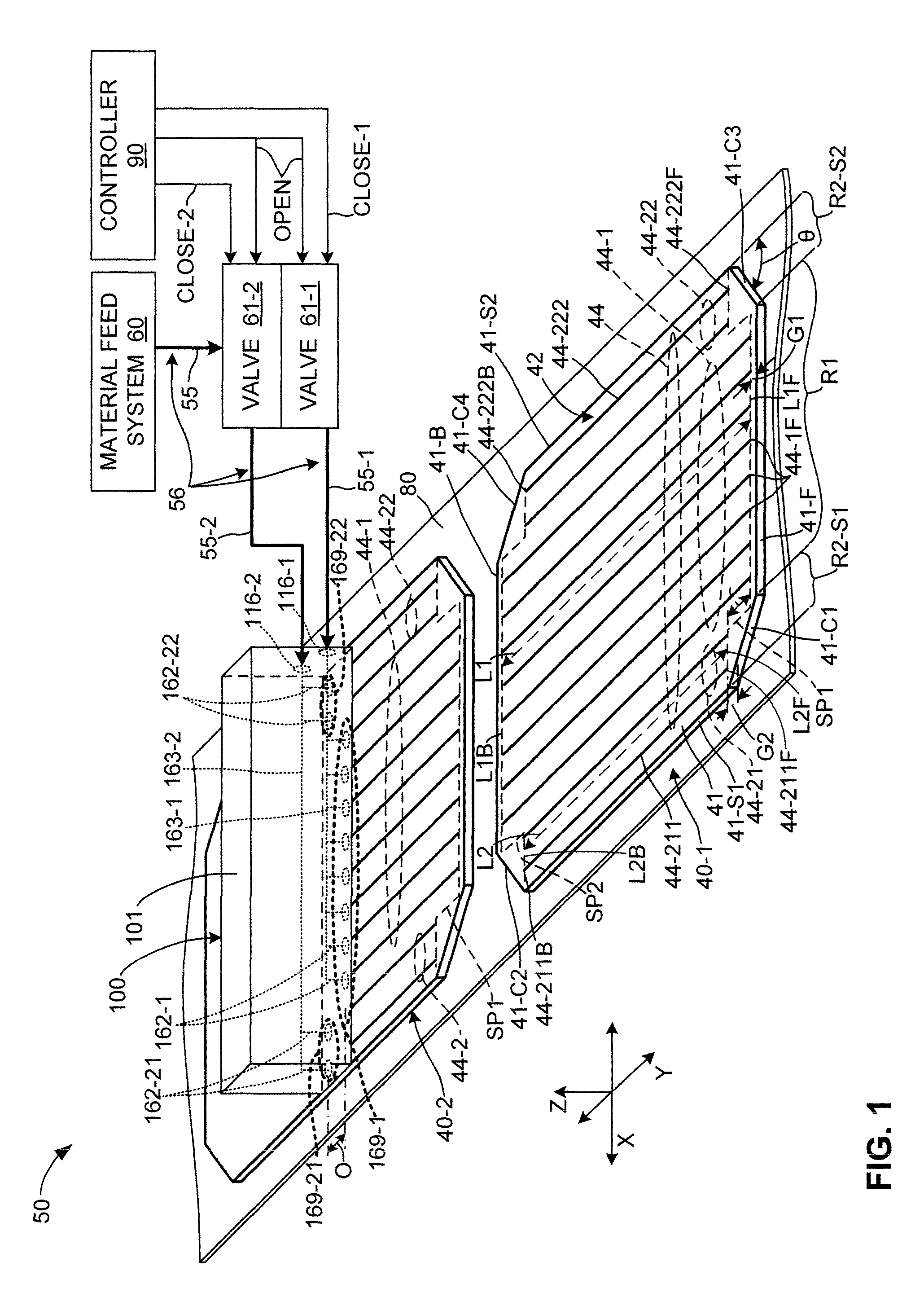
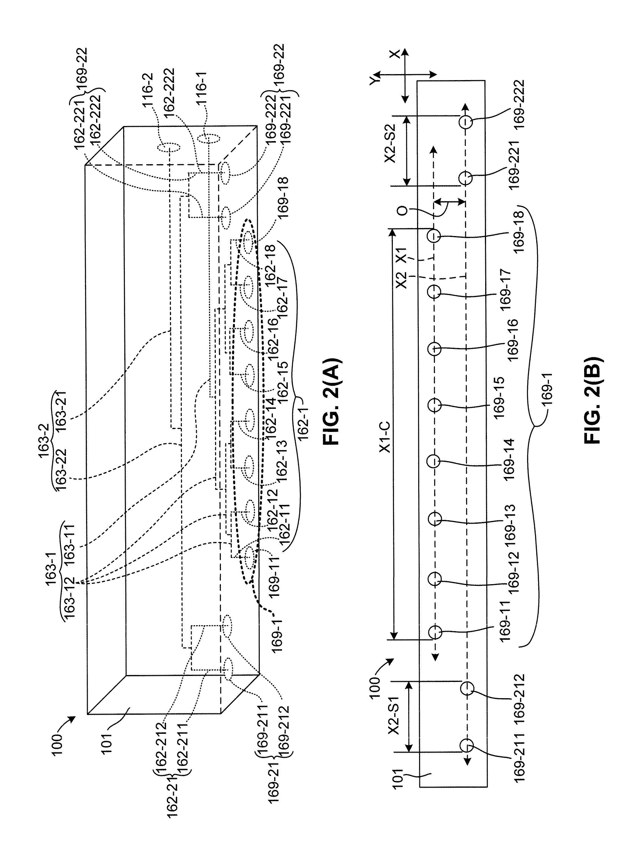
A solar cell extrusion printing system that uses a micro-extrusion printhead to print longer central gridlines and one or more pairs of shorter “side” gridlines such that end points of the gridline sets form step patterns on an octagonal (pseudo-square) substrate. The printhead includes a set of central nozzles that receive ink from a first valve by way of a first flow channel to print the longer central gridlines, and additional sets of side nozzles that receive ink from additional valves by way of additional flow channels to print the shorter “side” gridlines. The central nozzles have outlet orifices that offset in the process direction from side outlet orifices of the side nozzles. A start signal is simultaneously sent to the valves such that ink is substantially simultaneously extruded through both the central and side orifices, whereby the extruded ink produces gridline endpoints having the desired step pattern.

Description

FIELD OF THE INVENTION[0001]The present invention is related to the production of wafer-based electronic devices, and more particularly to the production of frontside metallization on H-pattern solar cells using micro-extrusion techniques.BACKGROUND[0002]FIG. 15 is a simplified diagram showing an exemplary conventional H-pattern contact solar cell 40H that converts sunlight into electricity by the photovoltaic effect. Solar cell 40H is formed on a semiconductor (e.g., poly-crystalline or mono-crystalline silicon) substrate 41H that is processed using known techniques to include an n-type doped upper region 41U and a p-type doped lower region 41L such that a pn-junction is formed near the center of substrate 41H. Disposed on a frontside surface 42H of semiconductor substrate 41H are a series of parallel metal gridlines (fingers) 44H (shown in end view) that are electrically connected to n-type region 41U. A substantially solid conductive layer 46 is formed on a backside surface 43 of...

Claims


Application Information

Patent Timeline
Patent Type & Authority Patents(United States)
IPC IPC(8): B05D5/00B05B7/06B05C11/00A21C3/00B05C3/02B05D5/12B29C45/00B29C48/05
CPCB29C47/0816B29C47/025H01L31/188B41J2/005B29C2947/926Y02E10/50B29C47/30B29C47/70B29C47/92H01L31/022433B29C48/92B29C48/154B29C48/2556B29C48/345B29C48/695B29C2948/926B29C48/05B05C5/027H01L31/18H01L31/042
Inventor COBB, CORIE LYNNSOLBERG, SCOTT E.
Owner XEROX CORP
Learn More