Multiple channel detection for time of flight mass spectrometer

a mass spectrometer and multi-channel technology, applied in mass spectrometers, isotope separation, particle separator tubes, etc., can solve the problem of inability to distinguish between signals, inability to accurately represent signal intensity, and inability to record ion arrival events or actual number of ions, etc. problem, to achieve the effect of improving the dynamic range and abundance sensitivity characteristi

Active Publication Date: 2014-11-11
MICROMASS UK LTD
View PDF6 Cites 26 Cited by
  • Summary
  • Abstract
  • Description
  • Claims
  • Application Information

AI Technical Summary

Benefits of technology

[0055]Furthermore, the ion detector according to the preferred embodiment of the present invention is particularly advantageous in that it has a significantly improved abundance sensitivity compared with state of the art ADC ion detectors and does not suffer from the problem of cross talk which is problematic for multiple anode TDC ion detectors.
[0060]The preferred embodiment allows an improvement in dynamic range and abundance sensitivity characteristic over conventional ion detectors.

Problems solved by technology

However, once an ion event has been recorded then there is a significant time interval (“dead time”) following the event during which time no further events may be recorded.
A disadvantage of the known ion detector with a one bit TDC detector is its inability to distinguish between a signal arising from the arrival of a single ion and a signal arising from the arrival of multiple ions at the same time since the resulting signal only crosses the threshold once irrespective of whether a single ion arrives or multiple ions arrive.
As a result, both of these situations result in only one event being recorded.
At high signal intensities the problem of being unable to discriminate between a single ion arrival event and multiple ions arriving, together with the problem of dead time effects results in some ion arrival events not being recorded or the actual number of ions being incorrectly recorded.
This results in an inaccurate representation of the signal intensity and also results in an inaccurate measurement of the arrival time.
These effects place an effective limit on the dynamic range of the detector system.
Whilst current state of the art ADC detector systems have several advantages over earlier TDC detector systems, ADC detector systems suffer from the problem that detection of low intensity signals is generally limited by electronic noise from the digitiser electronics, detector and amplifier used.
This effect limits the dynamic range of ADC detection systems.
Another disadvantage of a conventional ADC detector compared with a TDC detector is that the analogue width of the signal generated by a single ion adds to the width of the ion arrival envelope for a particular mass to charge ratio value in the final spectrum.
Single channel ADC systems have limited abundance sensitivity because mismatch of the high frequency detector impedance causes ringing after a large ion signal.
However, the threshold is not able to discriminate an artifact of a very large signal having a λ of 20.
As will therefore be readily appreciated by those skilled in the art, current commercial Time of Flight mass spectrometers employing ADC ion detectors suffer from the problem of having a limited abundance sensitivity.
However, despite certain advantages in using a detector arrangement comprising a double MCP, multiple anodes and multiple TDCs, such an arrangement remains only effective at detecting an ion signal at relatively low or moderate ion intensities.
However, the known multiple anode and multiple TDC ion detector arrangement is unable to provide sufficient gain for the detector electronics to function at high ion currents (i.e. >107 events / second).
Furthermore, the known detector arrangement also suffers from the problem of crosstalk between the metallic anodes which degrades the performance of the ion detector.
ADC based ion detector systems are also unable to operate with very bright ion sources i.e. >107 events / second.
Furthermore, ADC detector systems suffer from the problem of limited abundance sensitivity due to the effects of ringing after a large ion signal as discussed above.

Method used


Image

  • Multiple channel detection for time of flight mass spectrometer
  • Multiple channel detection for time of flight mass spectrometer
  • Multiple channel detection for time of flight mass spectrometer

Examples


Embodiment Construction

[0081]A known ion detector comprises a chevron arrangement of two Micro Channel Plates (“MCPs”) and a metallic anode detector. The two MCPs provide coulombic gains of 106 or more before digitization. Such an arrangement is effective in amplifying signals in an ion detector of a Time of Flight mass spectrometer up to an incoming ion rate of about 107 events / second. However, if the incoming ion rate increases above about 107 events / second then the double MCP arrangement becomes non linear as it is no longer possible to sustain the strip current required to maintain its gain.

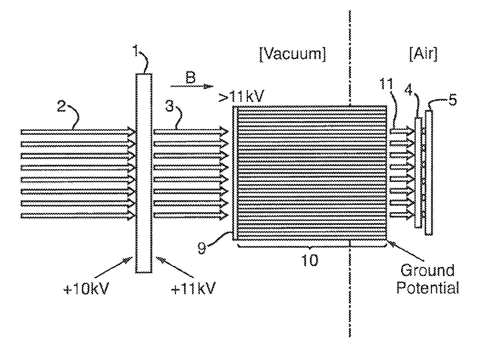
[0082]FIG. 2 shows an ion detector according to a preferred embodiment of the present invention. The ion detector preferably comprises a single MCP detector 1. Ions 2 impinge upon the front face of the single MCP detector 1 which results in a cascade of electrons 3 being emitted from the rear face of the MCP detector 1. The electrons 3 are directed onto an array of silicon photodiodes 4. Each photodiode 4 in the ph...


PUM


Abstract

An ion detector for a Time of Flight mass spectrometer is disclosed comprising a single Microchannel Plate 1 which is arranged to receive ions 2 and output electrons 3. The electrons 3 are directed onto an array of photodiodes 4 which directly detects the electrons 3. The output from each photodiode 4 is connected to a separate Time to Digital Converter provided on an ASIC 5.

Description

CROSS REFERENCE TO RELATED APPLICATIONS[0001]This application is the National Stage of International Application No. PCT / GB2012 / 052415, filed 28 Sep. 2012, which claims priority from and the benefit of United Kingdom Patent Application No. 1116845.7 filed on 30 Sep. 2011. The entire contents of these applications are incorporated herein by reference.BACKGROUND OF THE PRESENT INVENTION[0002]The present invention relates to an ion detector for a Time of Flight mass spectrometer, a Time of Flight mass analyser, a mass spectrometer, a method of detecting ions and a method of mass spectrometry.[0003]Time of Flight mass spectrometers comprising an ion detector coupled to a one bit Time to Digital Converter (“TDC”) are well known. Signals resulting from ions arriving at the ion detector which satisfy defined detection criteria are recorded as single binary values associated at a particular arrival time relative to a trigger event.[0004]It is known to use a fixed amplitude threshold to trig...

Claims


Application Information

Patent Timeline
Patent Type & Authority Patents(United States)
IPC IPC(8): H01J49/02H01J49/00H01J49/40
CPCH01J49/40H01J49/025H01J49/0031
Inventor HOYES, JOHN BRIANGILBERT, ANTHONY JAMESSUYAMA, MOTOHIRO
Owner MICROMASS UK LTD
Why Eureka
Try Eureka