
Control apparatus for vehicular power transmitting system

a control apparatus and transmission system technology, applied in the direction of electric devices, process and machine control, instruments, etc., can solve the problems of difficult to reduce the size and cost of an electric circuit including the smoothing capacitor, and reduce the output torque, so as to reduce the size and cost of an electric circuit, limit the reduction of output torque, and reduce the above-described electric motor torque.

Active Publication Date: 2014-12-09
TOYOTA JIDOSHA KK
View PDF42 Cites 7 Cited by
  • Summary
  • Abstract
  • Description
  • Claims
  • Application Information

AI Technical Summary

Benefits of technology

The present invention relates to a torque reduction control system for electric motors in vehicles. The invention limits the abrupt reduction of motor torque during torque reduction control to prevent damage to the inverter smoothing capacitor. This allows for a smaller and less expensive electric circuit design. The invention also monitors the motor torque to prevent the voltage of the inverter capacitor from exceeding its withstanding voltage. The torque reduction rate limiting range is determined based on the terminal voltage of the inverter capacitor or the change in motor output speed. This ensures high vehicle drivability and prevents damage to the inverter. The invention also reduces the rate of rise of the engaging force of the engaging side coupling device to prevent abrupt reduction of motor output and ensure stable operation of the inverter.

Problems solved by technology

An extreme increase of the above-described electric motor output reduction ratio may cause a failure of an electric power output circuit provided to supply electric power to the above-indicated inverter for the electric motor, to reduce its output following an output reduction of the electric motor, even when the extreme increase of the electric motor output reduction ratio takes place temporarily.
For this reason, it has been difficult to reduce the size and cost of an electric circuit including the smoothing capacitor.

Method used


Image

  • Control apparatus for vehicular power transmitting system
  • Control apparatus for vehicular power transmitting system
  • Control apparatus for vehicular power transmitting system

Examples


embodiments

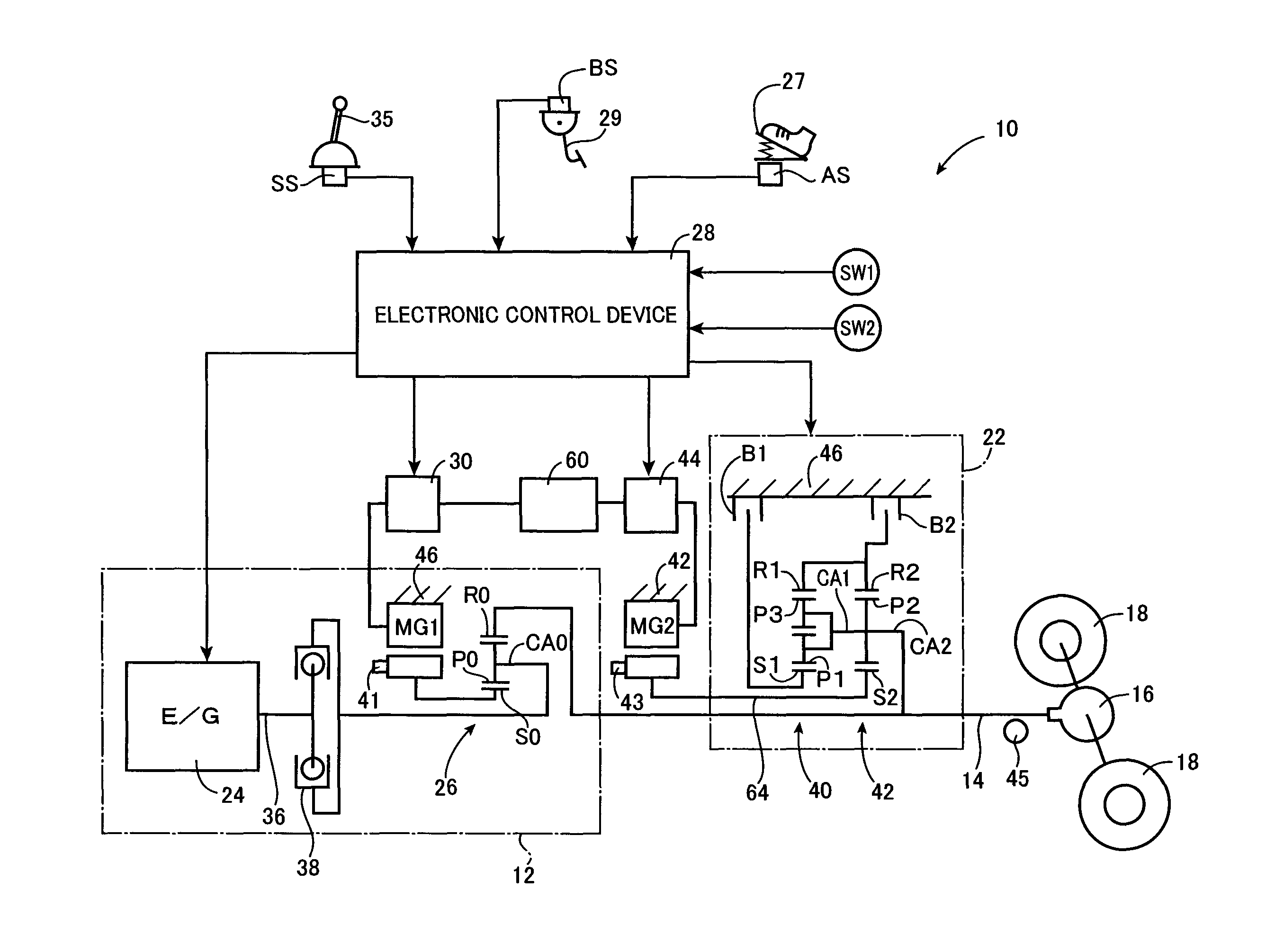
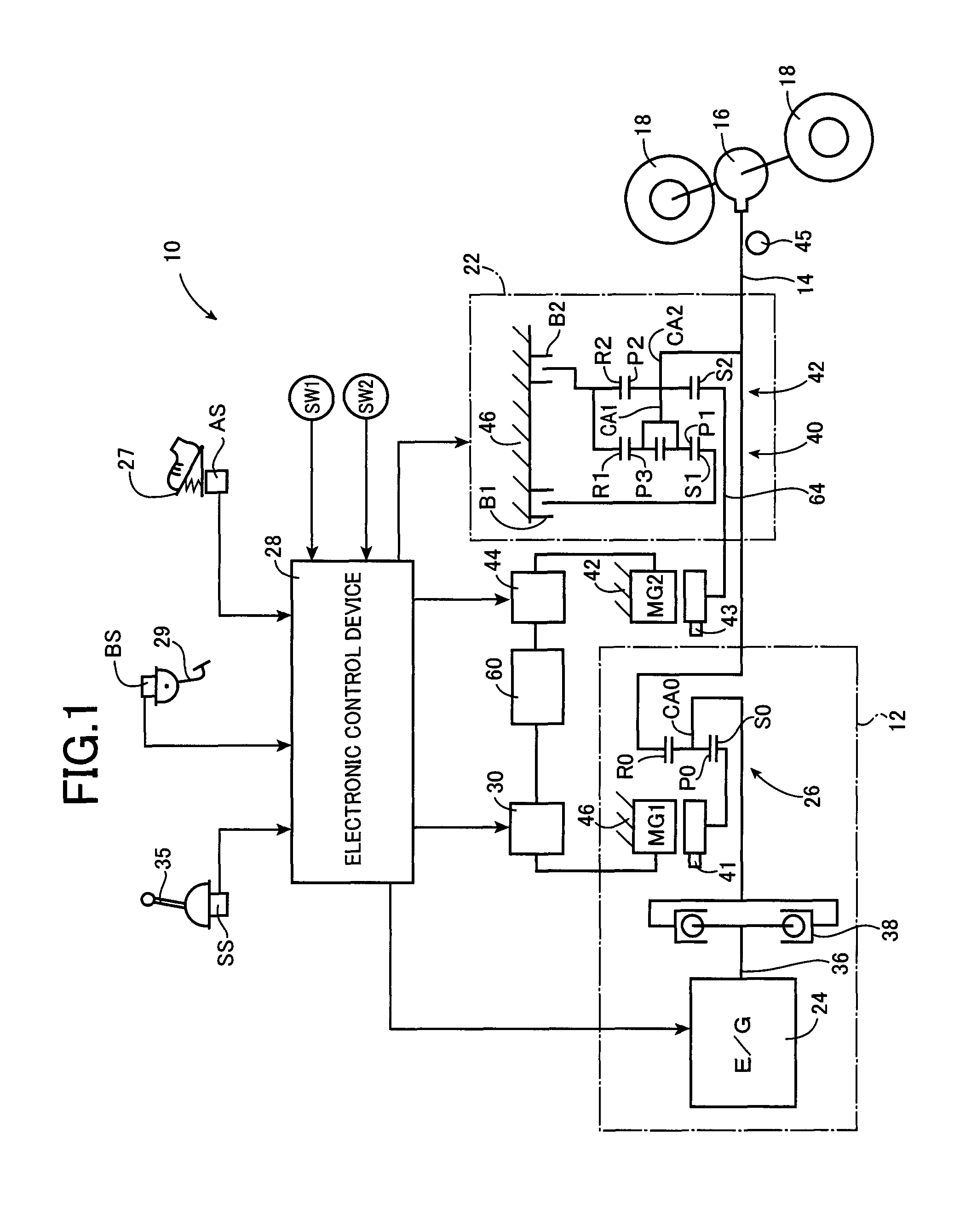
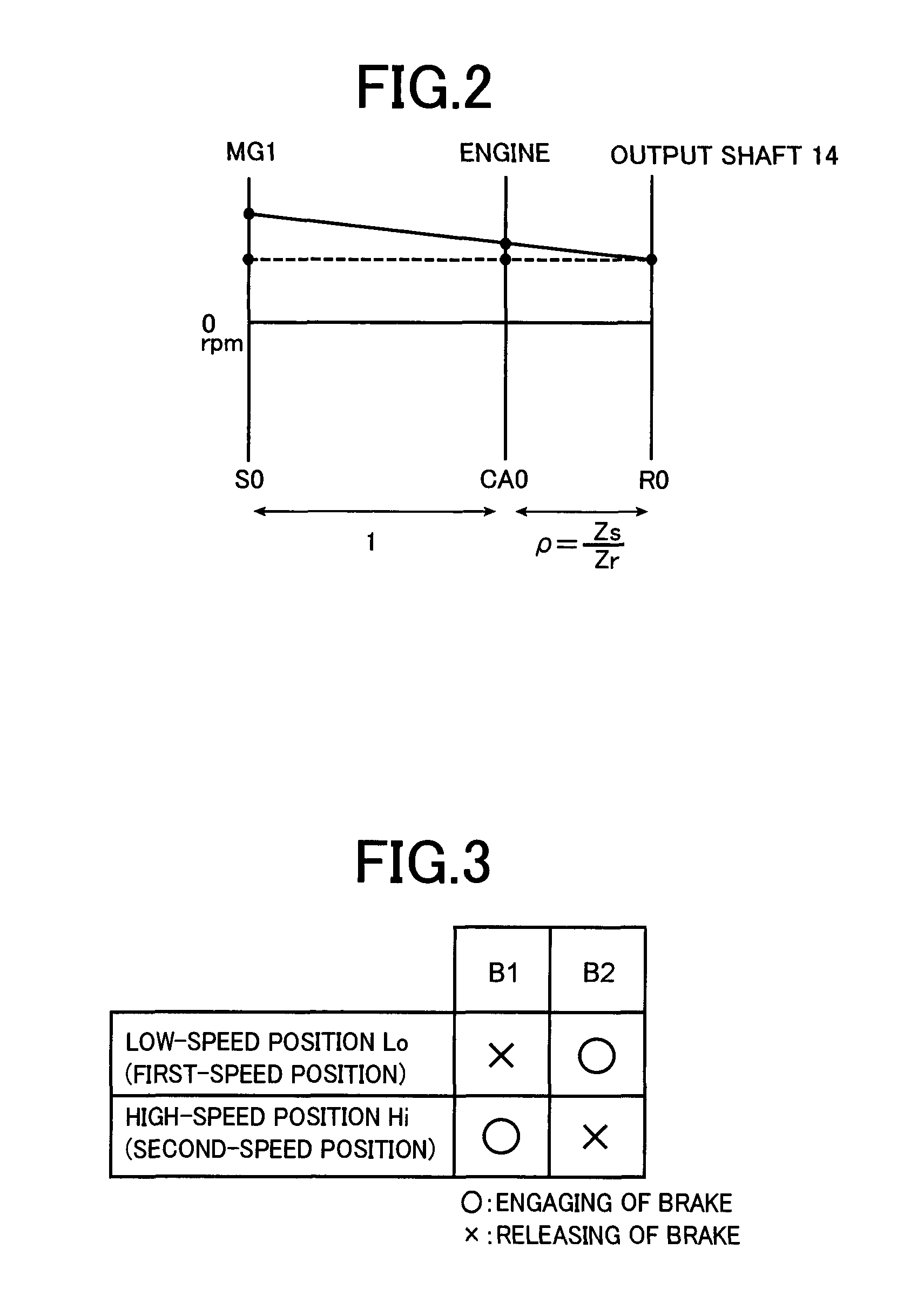
[0033]FIG. 1 is the schematic view for explaining a power transmitting system 10 of a hybrid vehicle (hereinafter referred to as “vehicular power transmitting system 10”) to which the present invention is applicable. As shown in FIG. 1, the vehicular power transmitting system 10 is provided with a main drive power source in the form of a first drive power source 12, a drive wheel-side output shaft 14 functioning as an output member (hereinafter referred to as “output shaft 14”), a differential gear device 16, a second electric motor MG2, and an automatic transmission 22. In the vehicular power transmitting system 10, a torque of the first drive power source 12 is transmitted to the output shaft 14, and is then transmitted from the output shaft 14 to a pair of right and left drive wheels 18 through the differential gear device 16. Further, the vehicular power transmitting system 10 is configured such that the second electric motor MG2 is operatively connected to the output shaft 14 t...


PUM


Abstract

It is provided a control apparatus for a vehicle provided with an electric motor power source, an inverter, an electric motor, an inverter smoothing capacitor, and a step-variable automatic transmission, the control apparatus being configured to implement a torque reduction control, and to implement a torque reduction limitation control to limit reduction of an output torque of the electric motor to within a range in which a terminal voltage of the inverter smoothing capacitor will not exceed a predetermined withstanding voltage of the inverter and to limit the reduction of the output torque by limiting an amount of change of the output torque per unit time during the reduction of the output torque in the torque reduction control, to within a predetermined torque reduction rate limiting range, and wherein the torque reduction rate limiting range is determined upon initiation of a shifting action of the automatic transmission.

Description

CROSS-REFERENCE TO RELATED APPLICATIONS[0001]This application is a Continuation-in-Part of International Application No. PCT / JP2009 / 071704, filed Dec. 26, 2009, the content of which is incorporated herein by reference.TECHNICAL FIELD[0002]The present invention relates to techniques for controlling an output torque of an electric motor provided on a vehicle as a drive power source.BACKGROUND ART[0003]There is well known a vehicular power transmitting system provided with an electric motor as a drive power source, and an automatic transmission constituting a part of a power transmitting path between the electric motor and drive wheels, as commonly seen in a hybrid vehicle or an electric vehicle. Patent Document 1 discloses an example of such a vehicular power transmitting system.[0004]A control apparatus for the vehicular power transmitting system disclosed in the Patent Document 1 is configured to implement a torque reduction control of the above-indicated electric motor to temporari...

Claims


Application Information

Patent Timeline
Patent Type & Authority Patents(United States)
IPC IPC(8): B60L11/00B60W20/00B60W30/19G06F7/00B60L11/14B60W10/08B60W10/115B60K6/445B60L3/00G05D1/00G06F17/00B60L15/20B60L9/00B60L50/10B60L50/16
CPCB60W20/00B60L2240/527B60K6/445B60L15/2054B60L2240/423B60W30/19Y10S903/903Y02T10/7077B60W10/08B60L11/14B60L3/003Y02T10/642Y02T10/6239B60W10/115Y02T10/70Y02T10/7275B60L50/10B60L50/16Y02T10/62Y02T10/64Y02T10/7072Y02T10/72B60W2710/083
Inventor SATO, DAIKIUEJIMA, TAIYOSHIIBA, KAZUYUKIYAMAMURA, NORIHIRO
Owner TOYOTA JIDOSHA KK
Learn More