Tilted structures to reduce reflection in laser-assisted TAMR

a laser-assisted tamr and tilting structure technology, applied in the field of magnetic read/write heads, can solve the problems of reducing the field gradient and broader field profile, reducing the thermal instability of the extremely small region of magnetic materials, and satisfying the requirements of simultaneously

Active Publication Date: 2014-12-30
HEADWAY TECH INC
View PDF8 Cites 5 Cited by
  • Summary
  • Abstract
  • Description
  • Claims
  • Application Information

AI Technical Summary

Benefits of technology

[0018]It is an object of this disclosure to provide an optical-laser-driven TAMR device in which the effects of back reflected laser light are eliminated.
[0019]It is a further object of this disclosure to provide stable laser power to a TAMR slider as a result of eliminating back reflected light.
[0020]It is still a further object of this disclosure to reduce variations in media temperature that arise as a result of the adverse effects of back reflected light in a TAMR slider.
[0021]It is yet a further object of this disclosure to achieve the previous objects while also reducing recording transition shifts due to thermal spot variations and to ultimately improve the linear density capability of the recording process while also reducing adjacent track interference resulting from laser power fluctuations.
[0023]These objects will be met by means of a tilted [laser / waveguide / plasmon generator] structure (separately tilted or in various combinations), to be shown and described in detail in FIGS. 2-10, below. In this tilted structure, the centerline along the optical axis (direction of radiation propagation) of the waveguide is not perpendicular to either one or both end surfaces of the slider (i.e., the backside surface or the ABS surface). Additionally, the plasmon generator may or may not be tilted. Further, a laser diode (LD) is formed in which the axis of the diode cavity (350), which is typically a Fabry-Perot type cavity resonator, may also be tilted relative to its mounting surface on the backside of the waveguide, providing yet a further mechanism by which reflected light produced by the laser is prevented from reflecting back into the laser cavity. In this way, the reflected light from these surfaces can be completely suppressed.
[0026]In addition, the plasmon generator structure can also be tilted to eliminate the back reflected light during the light coupling process from the waveguide to the plasmon generator. This reflection occurs as a result of the change in the effective mode index along the light propagation direction when the plasmon generator is placed near the WG and the PG shape changes along the WG.

Problems solved by technology

This latter effect is the thermal instability of the extremely small regions of magnetic material on which information must be recorded, in order to achieve the required data densities.
1. The need for a stronger writing field that is necessitated by the highly anisotropic and coercive magnetic media.
2. The need for a smaller write head of sufficient definition to produce the high areal write densities, which write heads, disadvantageously, produce a smaller field gradient and broader field profile.
Satisfying these requirements simultaneously may be a limiting factor in the further development of the present magnetic recording scheme used in state of the art hard-disk-drives (HDD).
If that is the case, further increases in recording area density may not be achievable within those schemes.
However, in what follows, we will not eliminate the possibility that the electromagnetic radiation may be radiation that is other than optical frequency, in which case the conditions for suppression of reflections will have to be calculated using suitable boundary conditions at the interfaces.
These unwanted variations cause changes in the temperature of the recording medium, introduce jitter into the recording bits and cause track-width changes to the recording process.
In addition, the power ratio between the emitting side and the back side of the LD varies due to the reflected radiation which makes it very difficult, if not impossible monitor light intensity from the back side by means of an integrated photo-diode (PD) in order to achieve a feedback-controlled constant power output at the ABS end.
If this is so, the reflected light from these two surfaces will be unable to propagate backwards through the WG channel to reach the LD cavity and have an adverse impact.

Method used


Image

  • Tilted structures to reduce reflection in laser-assisted TAMR
  • Tilted structures to reduce reflection in laser-assisted TAMR
  • Tilted structures to reduce reflection in laser-assisted TAMR

Examples


Embodiment Construction

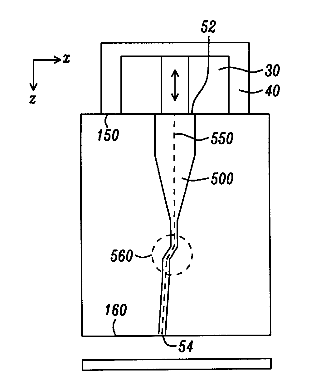
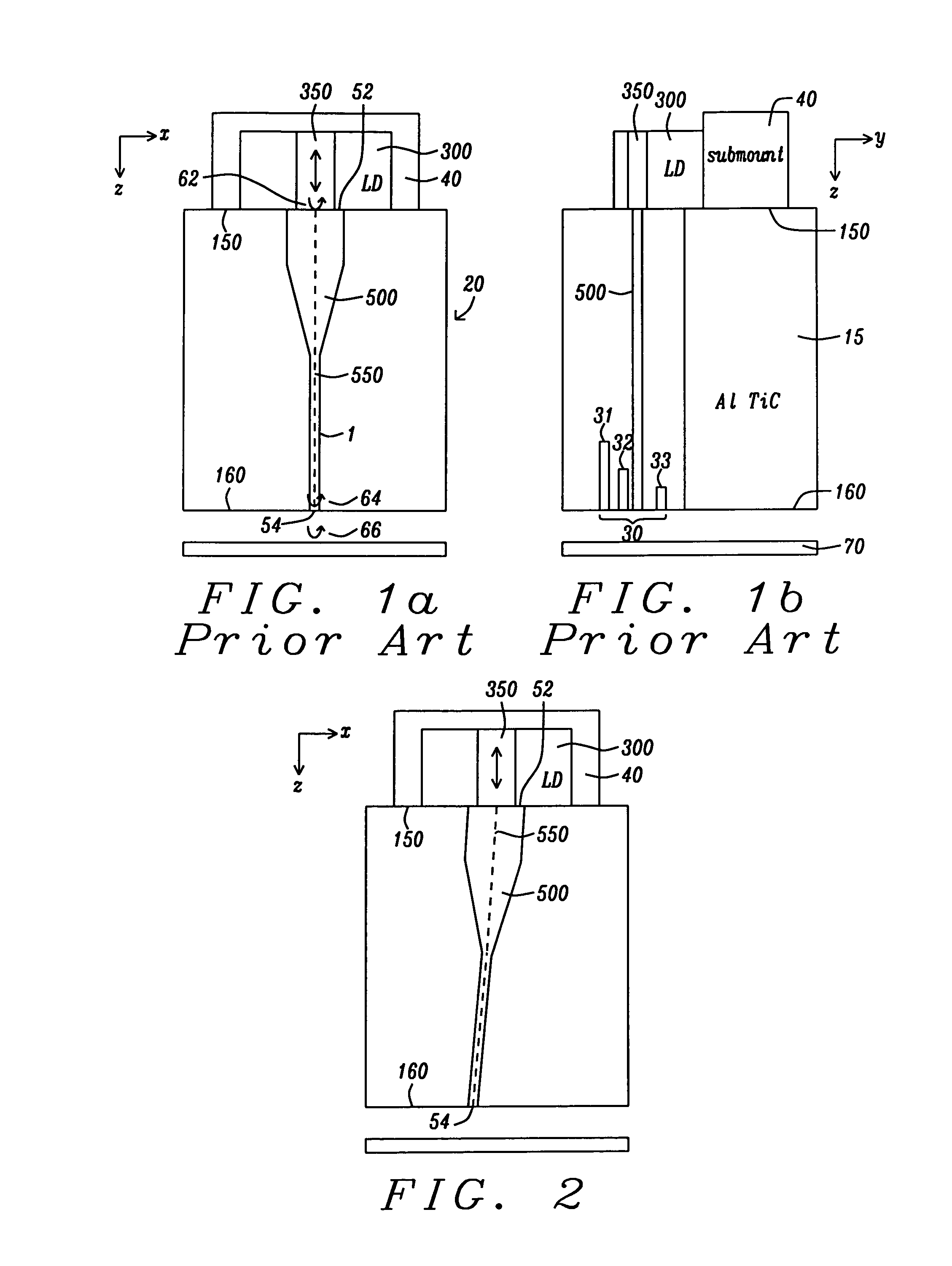
[0040]The details of the following disclosure will be understood by first referring to FIG. 2, which shows, schematically, a basic TAMR slider structure similar to that shown in FIG. 1(a), but with the waveguide (500) now inclined relative to the vertical (z-direction) so that the center line (550) through the waveguide, along the light-propagation direction, makes a uniform angle to the normal (which is the z-direction) of both the back end surface (150) of the slider and the ABS surface of the slider. The tilted waveguide has the same y-z cross-section as the waveguide shown in FIG. 1(b), but both the top surface (52), in the back end plane of the slider, and the bottom surface (54), in the ABS plane (160) of the slider, are tilted at the same angle to the normal (the z-axis).

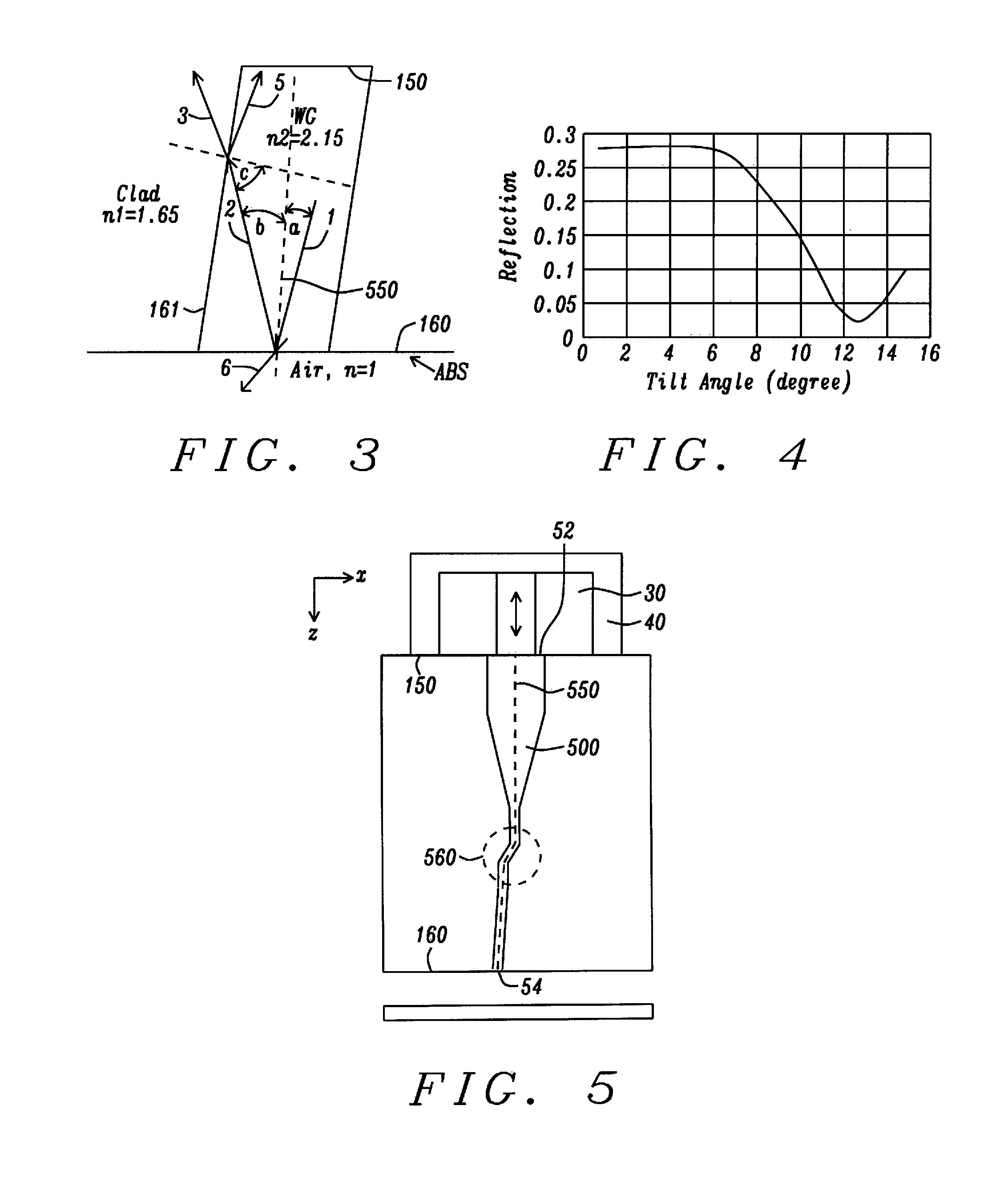
[0041]Referring next to FIG. 3, there is shown a diagram schematically illustrating an application of Snell's Law of reflection to the back reflection of the optical laser light at the interface between the w...


PUM

PropertyMeasurementUnit
angleaaaaaaaaaa
angleaaaaaaaaaa
widthaaaaaaaaaa

Abstract

A TAMR (Thermal Assisted Magnetic Recording) write head uses the energy of optical-laser excited surface plasmons in a plasmon generator to locally heat a magnetic recording medium and reduce its coercivity and magnetic anisotropy. The optical radiation is transmitted to the plasmon generator by means of a waveguide, whose optical axis (centerline) is tilted relative to either or both the backside surface normal and ABS surface normal in order to eliminate back reflections of the optical radiation that can adversely affect the properties and performance of the laser. Variations of the disclosure include tilting the plasmon generator, the waveguide and the laser diode.

Description

BACKGROUND[0001]1. Technical Field[0002]This invention relates to magnetic read / write heads that employ TAMR (thermally assisted magnetic recording) using laser energy to heat magnetic media having high coercivity and high magnetic anisotropy. More particularly, it relates to methods that reduce reflections of the laser radiation back to the TAMR structures.[0003]2. Description of the Related Art[0004]Magnetic recording at area data densities of between 1 and 10 Tera-bits per in2 involves the development of new magnetic recording media, new magnetic recording heads and, most importantly, a new magnetic recording scheme that can delay the onset of the so-called “superparamagnetic” effect. This latter effect is the thermal instability of the extremely small regions of magnetic material on which information must be recorded, in order to achieve the required data densities. A way of circumventing this thermal instability is to use magnetic recording media with high magnetic anisotropy a...

Claims


Application Information

Patent Timeline
Patent Type & Authority Patents(United States)
IPC IPC(8): G11B5/127G11B13/04G11B11/00
CPCG11B13/04G11B5/314G11B5/127G11B2005/0021G11B5/6088G11B5/4866G11B5/6005Y10T29/49032
Inventor JIN, XUHUILOU, XIAOHUASMYTH, JOEDOVEK, MORIS
Owner HEADWAY TECH INC
Why Eureka
Try Eureka