DC power supply apparatus

a power supply and power supply technology, applied in the direction of converting intermediately to dc, reducing the harmonic current of the power supply, and ensuring the effect of power supply efficiency

Inactive Publication Date: 2015-01-20
AUTO TECH GRP LLC
View PDF30 Cites 14 Cited by
  • Summary
  • Abstract
  • Description
  • Claims
  • Application Information

AI Technical Summary

Benefits of technology

[0013]Accordingly, because a semiconductor element, which is formed by using the Schottky junction formed between metal and silicon carbide (SiC) or gallium nitride (GaN) and has the withstanding voltage property with respect to the voltage of the AC power supply, is employed as the rectifying element cooperatively operating with the switching operation of the semiconductor switching element, it is possible to obtain a DC power supply apparatus with a high efficiency, which realizes the increase of the switching frequency, is high in the power factor of the power supply and is reduced in the harmonic current of the power supply.

Problems solved by technology

In a rectifying circuit contained in a DC power supply apparatus of related art, since an input current inputted into the DC power supply apparatus from an AC power supply can not be rectified synchronously with the voltage of the AC power supply, the power factor of the power supply is low and the reactive power amount is large.
That is, there arises a problem that the electric power utilization factor is low.
Further, the DC power supply apparatus of the related art has a problem that the waveform of the input current inputted from the AC power supply deforms from the sinusoidal waveform, that is, the input current contains much harmonic current component.
Thus, there arises a problem that the operation of other apparatuses connected to the same power supply system is interfered and the power transmission facility is damaged.
In this case, since a large current ripple occurs due to the switching operation on the input current from the AC power supply, there arises a problem that a portion for removing the current ripple component, that is, a filter circuit is required.
Further, when the switching frequency is low, since the time control of the current and voltage according to a PWM control becomes rough, there arise problems that the input current from which the current ripple has been removed can not maintain the sinusoidal waveform and is distorted and further a phase shift occurs between the input current and the voltage of the power supply.
Furthermore, since the filter circuit for removing the large current ripple component largely influences on the phase of the input current, the waveform of the input current is deformed or distorted.
However, in the case of increasing the switching frequency of the DC power supply apparatus to be connected to the AC power supply, even when the voltage of the AC power supply is applied so as to follow the high-speed switching operation of the semiconductor switching elements, there is a problem that there is no rectifying element having a high withstanding voltage and current which can prevent the dielectric breakdown thereof.
Further, when the switching frequency is increased in the constituent components of the related art, the loss of each of the semiconductor elements, that is, the rectifying elements and the semiconductor switching elements on a path for flowing the current from the DC power supply apparatus becomes large.
Thus, there arise problems that the efficiency of the DC power supply apparatus reduces and the semiconductor elements can not withstand heat generated by the loss and are burnt.
Further, when the switching frequency is increased, since the amount of heat generation increases due to the increase of the loss of the semiconductor elements of the DC power supply apparatus, there arises a problem that the size and the cost of a cooling apparatus increases.
Furthermore, since high-frequency noise is generated due to the high-speed switching operation of the semiconductor elements of the DC power supply apparatus, there arise problems that another apparatus except for the DC power supply apparatus is erroneously operated or the DC power supply apparatus itself is erroneously operated.

Method used


Image

  • DC power supply apparatus
  • DC power supply apparatus
  • DC power supply apparatus

Examples


first exemplary embodiment

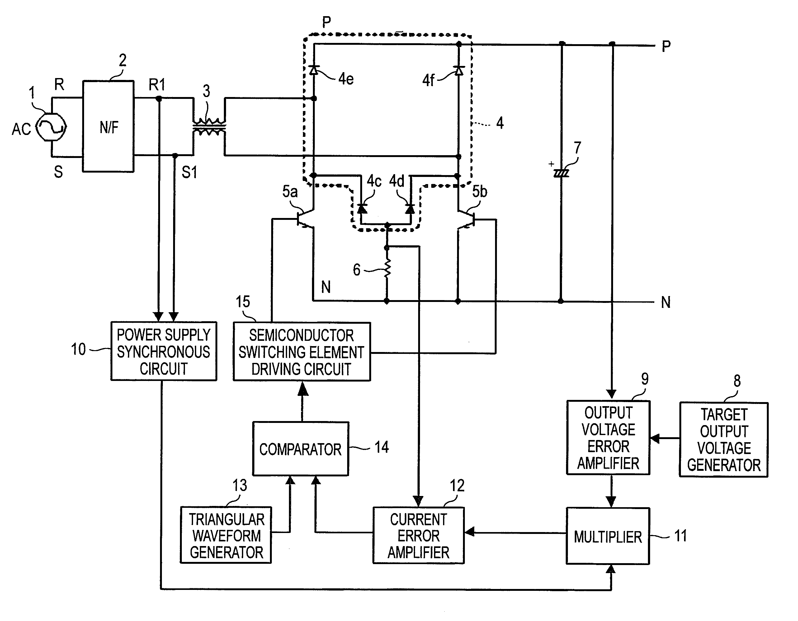
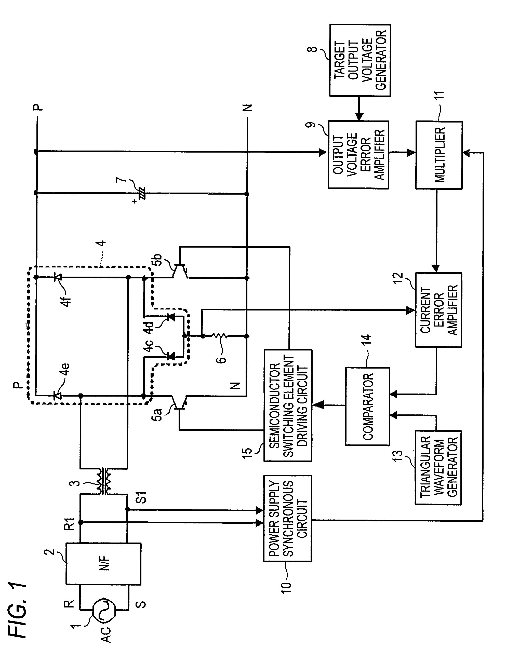
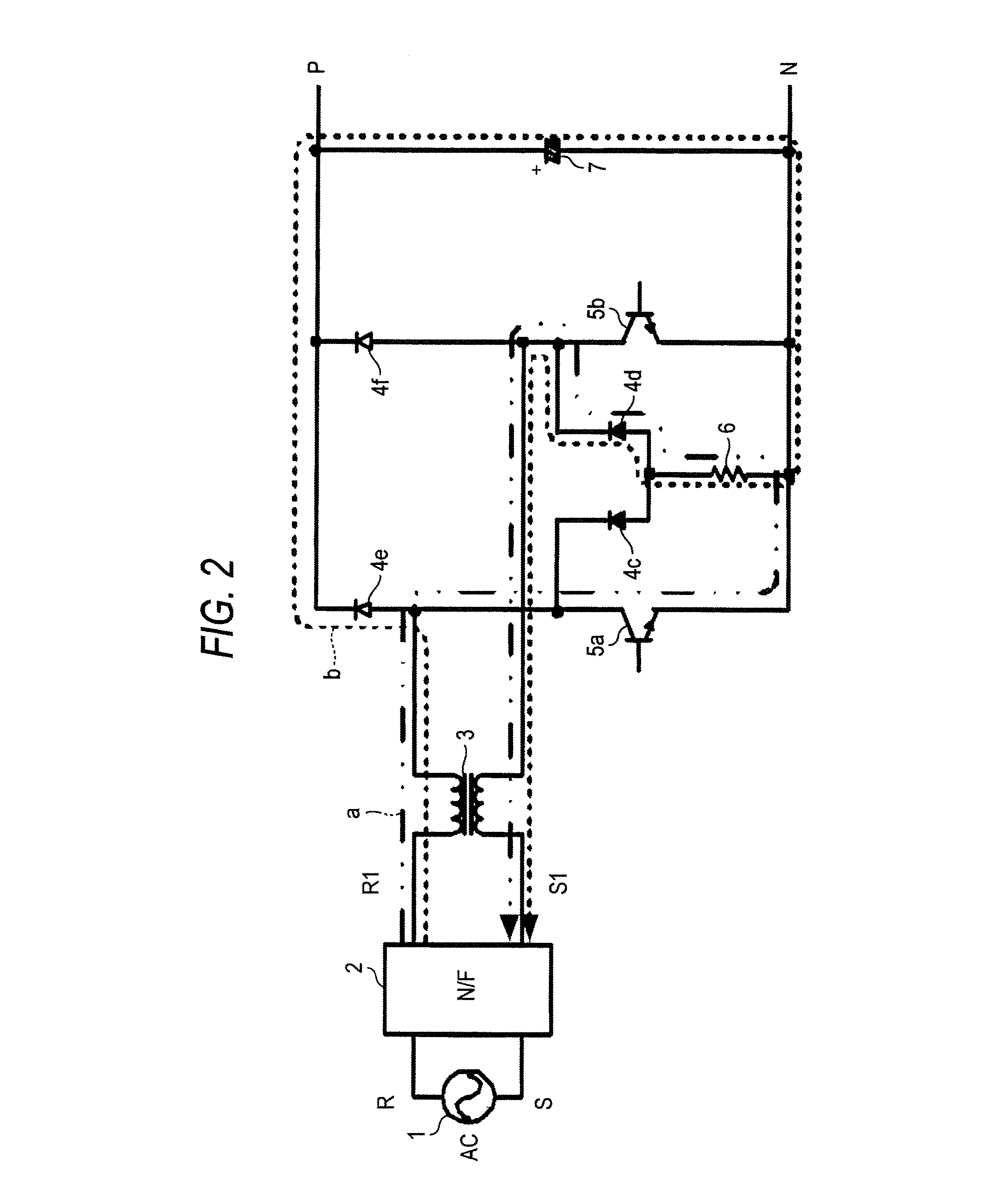
[0023]FIG. 1 is a diagram showing a circuit configuration of a half-bridge type converter circuit according to a first exemplary embodiment of the present invention, which is a DC power supply apparatus that is used for a household electrical appliance such as an air conditioner and performs the improvement of the power factor of the power supply, the reduction of the harmonic current of the power supply and the adjustment of a DC output voltage. The description hereinafter is based on the half-bridge type converter circuit. An AC power supply 1 is connected to a rectifying circuit 4 via a noise filter 2 and a reactor 3. The rectifying circuit 4, that is, a diode bridge circuit is configured by rectifying elements, that is, diodes 4c, 4d, 4e and 4f in a manner that the rectifying elements 4e, 4f are connected to the positive electrode terminal side of the rectifying circuit 4 and the rectifying elements 4c, 4d are connected to the negative electrode terminal side of the rectifying c...


PUM


Abstract

A DC power supply apparatus comprising: a rectifying circuit including, a first rectifying portion, a second rectifying portion, a third rectifying portion and a fourth rectifying portion; a current detection portion; a first switching portion; and a second switching portion; wherein each of the first rectifying portion cooperatively operating with the first switching portion and the second rectifying portion cooperatively operating with the second switching portion is a semiconductor element which is formed by using a Schottky junction formed between silicon carbide or gallium nitride and metal and has a withstanding voltage property with respect to a voltage of an AC power supply.

Description

CROSS-REFERENCE TO RELATED APPLICATIONS[0001]This application claims priority from Japanese Patent Application No. 2010-024185 filed on Feb. 5, 2010, the entire contents of which are incorporated herein by reference.TECHNICAL FIELD[0002]Aspects of the present invention relate to a DC power supply apparatus for performing AC / DC conversion.BACKGROUND[0003]In a rectifying circuit contained in a DC power supply apparatus of related art, since an input current inputted into the DC power supply apparatus from an AC power supply can not be rectified synchronously with the voltage of the AC power supply, the power factor of the power supply is low and the reactive power amount is large. That is, there arises a problem that the electric power utilization factor is low. The reactive power component is the power returned to the power supply side without being consumed by a load side connected via the DC power supply apparatus, among the power supplied from the power supply. The presence of the...

Claims


Application Information

Patent Timeline
Patent Type & Authority Patents(United States)
IPC IPC(8): H02M1/12
CPCY02B70/1483H02M7/219Y02B70/10
Inventor AMANO, KATSUYUKISUZUKI, DAISUKESAITO, KATSUHIKO
Owner AUTO TECH GRP LLC
Why Eureka
Try Eureka