Random mat and fiber-reinforced composite material

a composite material and mat technology, applied in the field of random mats and can solve the problems of discontinuous discharge of fibers from cutters, increase the cost of fiber reinforced composite materials, and deterioration of surface appearance, and achieve excellent surface appearance quality and excellent reduction of thickness and isotropy

Active Publication Date: 2015-02-03
TEIJIN LTD
View PDF34 Cites 53 Cited by
  • Summary
  • Abstract
  • Description
  • Claims
  • Application Information

AI Technical Summary

Benefits of technology

[0020]The random mat of the invention is preferably usable as a preform for preparing a shaped fiber-reinforced composite material, and a fiber-reinforced composite material excellent in surface appearance quality can be provided thereby. Further, a fiber-reinforced composite material excellent in reduction in thickness and isotropy can be provided by using the random mat of the invention as the preform. The random mat of the invention, therefore, can be used as the preform for various constituent members, for example, inner plates, outer plates and constituent members of automobiles, various electric appliances, frames and boxes of machines, and the like.

Problems solved by technology

Generally, in case of the fabrics made of the continuous fibers, the UD sheets and the like, complicated layering steps such as layering at various angles, for example, at 0 / +45 / −45 / 90, because of anisotropy of the fibers, and further plane-symmetrical layering for preventing warpage of shaped products, have become one of the factors that increase the cost of the fiber-reinforced composite materials.
However, when the distance between blades of the cutter is increased in order to lengthen the fiber length, the cut frequency decreases, and thereby results in discontinuous discharge of the fibers from the cutter.
In particular, when the mat having a low fiber areal weight of fibers is prepared, the unevenness in thickness becomes significant, which has caused a problem of deteriorated surface appearance.
On the other hand, another factor that increases the cost of the fiber-reinforced composite materials is that the molding time is long.
However, even when the RTM molding method is adopted, it takes 10 minutes or more until one part is molded.
However, the thermoplastic resin generally has high viscosity compared to the thermosetting resin, so that the time to impregnate the molten resin into the fiber base material becomes long.
As a result, there has been a problem that the takt time until molding increases.
In such thermoplastic stamping molding, the fibers and the resin are allowed to flow in the mold, so that there have been problems of failing to produce a thin-walled one and fiber orientation is disturbed as the orientation becomes beyond control.

Method used


Image

  • Random mat and fiber-reinforced composite material
  • Random mat and fiber-reinforced composite material
  • Random mat and fiber-reinforced composite material

Examples


example 1

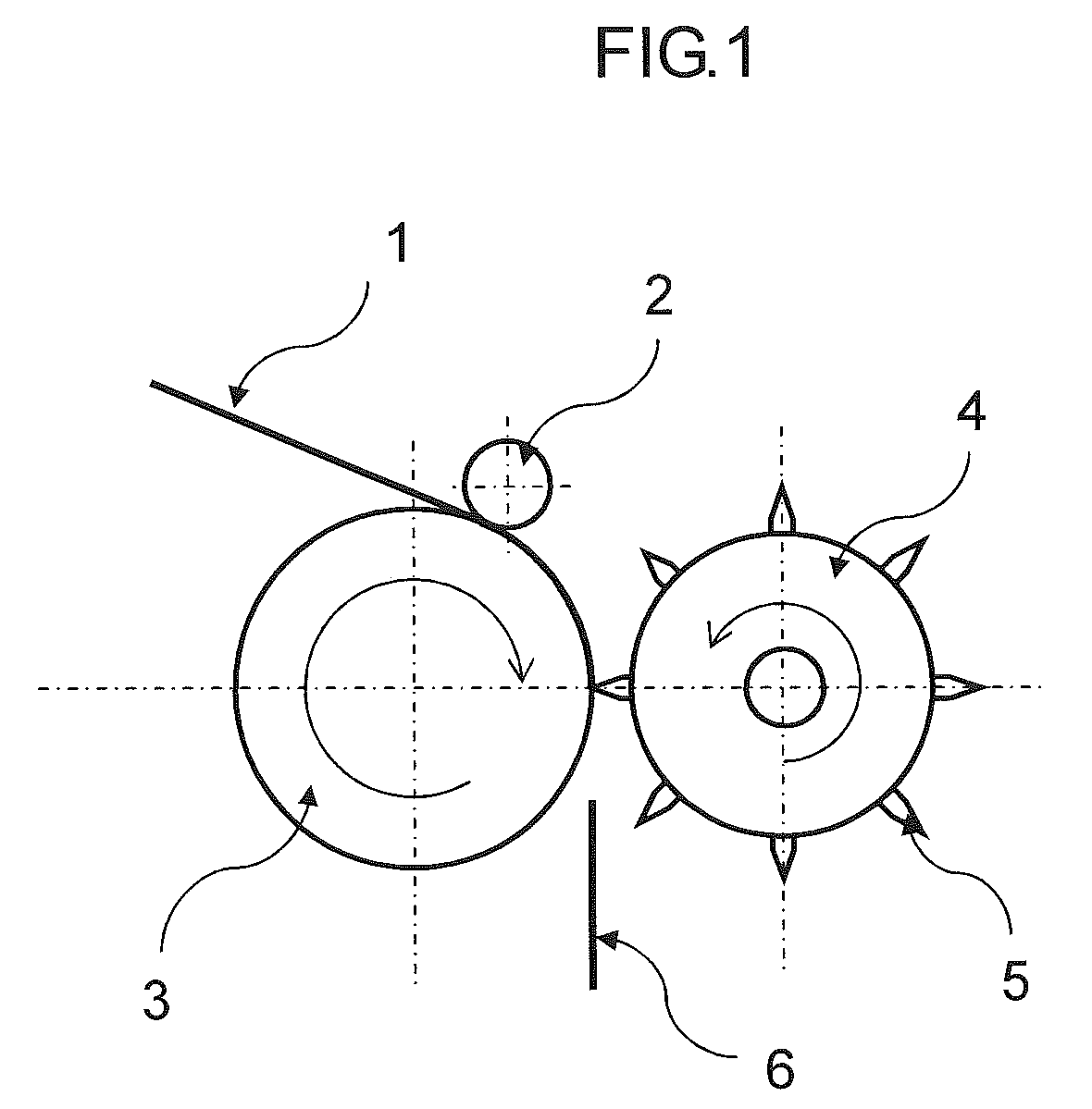
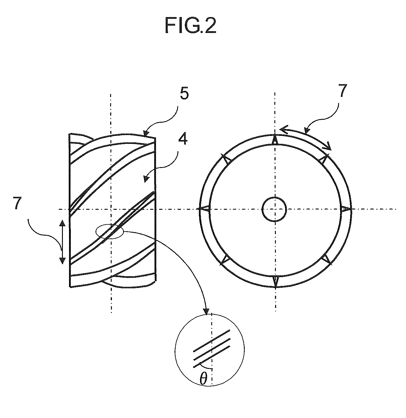
[0096]As reinforcing fibers, there were used a strand of carbon fibers, “Tenax” (registered trade mark) STS40-24KS (average fiber diameter: 7 μm, strand width: 10 mm) manufactured by Toho Tenax Co., Ltd., and the strand was widened to a width of 20 mm. As a cutting device, there was used a rotary cutter in which a spiral knife was arranged on a surface thereof, using a cemented carbide. At this time, θ in the following formula (3) was 63 degrees, and the pitch of blades was adjusted to 10 mm so as to cut the reinforcing fibers to a fiber length of 10 mm.

Pitch of blades=width of a reinforcing fiber strand×tan(90−θ)  (3)

[0097]wherein θ is the angle between the circumferential direction and the knife.

[0098]For preparing a fiber opening device, SUS 304-made nipples different in diameter were welded to prepare a double tube and small holes were made in an inner tube. Compressed air was supplied between the inner tube and an outer tube using a compressor. At this time, the wind velocity o...

example 2

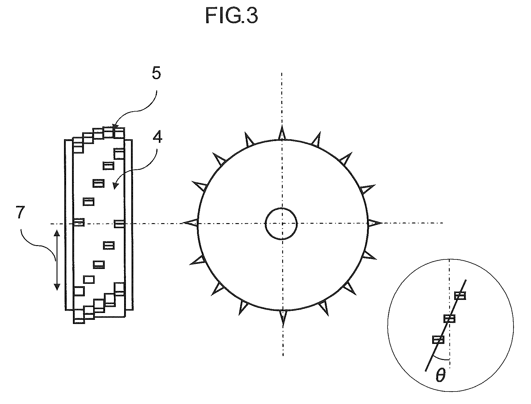
[0102]As reinforcing fibers, there were used carbon fiber strands, “Tenax” (registered trade mark) IMS60-12K (average fiber diameter: 5 μm, strand width: 6 mm) manufactured by Toho Tenax Co., Ltd. As a cutting device, there was used a rotary cutter in which a spiral knife was arranged on a surface thereof, using a cemented carbide. As this rotary cutter, there was used a fiber separating cutter in which blades parallel to a fiber direction as shown in FIG. 4 were provided at 0.5-mm intervals, for the purpose of miniaturizing the fiber bundles. At this time, θ in the above-mentioned formula (3) was 17 degrees, and the pitch of blades was adjusted to 20 mm. The reinforcing fibers were cut to a fiber length of 20 mm. As a fiber opening device, a tube having small holes was prepared, and compressed air was supplied thereto using a compressor. The wind velocity of air from the small holes was adjusted to 150 m / sec. This tube was disposed just under the rotary cutter, and further, a taper...

example 3

[0106]As reinforcing fibers, there were used glass fiber strands, EX-2500 (average fiber diameter: 15 μm, strand width: 9 mm) manufactured by Nippon Electric Glass Co., Ltd. As a cutting device, there was used a rotary cutter in which short blades in a 90-degree direction to the fibers were obliquely disposed and a fiber separating knife was arranged on a surface thereof, using a cemented carbide. The width of the knife was 1 mm, and further, blades parallel to a fiber direction were provided between the knives, for the purpose of miniaturizing the fiber bundles. At this time, θ in the above-mentioned formula (3) was 10 degrees, and the pitch of blades was adjusted to 50 mm. The reinforcing fibers were cut to a fiber length of 50 mm. As a fiber opening device, there was used the same device as used in Example 1. The wind velocity of air from the small holes was adjusted to 350 m / sec by decreasing the pressure of the compressor. This tube was disposed just under the rotary cutter, an...


PUM

PropertyMeasurementUnit
lengthaaaaaaaaaa
lengthaaaaaaaaaa
lengthaaaaaaaaaa

Abstract

There is provided a random mat of the present invention including: reinforcing fibers having an average fiber length of 5 to 100 mm; and a thermoplastic resin,wherein a fiber areal weight of the reinforcing fibers is from 25 to 3,000 g / m2, for a reinforcing fiber bundle (A) including the reinforcing fibers equivalent to or more than a critical single fiber number defined by formula (1), a ratio of the reinforcing fiber bundle (A) to a total amount of the reinforcing fibers in the mat is from 30 vol % to less than 90 vol %, and an average number (N) of the reinforcing fibers in the reinforcing fiber bundle (A) satisfies formula (2):Critical single fiber number=600 / D  (1)0.7×10⁴ / D2<N<1×10⁵ / D2  (2)wherein D is an average fiber diameter (μm) of single reinforcing fibers.

Description

CROSS REFERENCE TO RELATED APPLICATION[0001]This is a continuation of International Application No. PCT / JP2011 / 070314 filed on Aug. 31, 2011, and claims priority from Japanese Patent Application No. 2011-019891, filed on Feb. 1, 2011, the entire disclosures of which are incorporated herein by reference.TECHNICAL FIELD[0002]The present invention relates to a random mat usable as a preform of a fiber-reinforced composite material shaped product, and a fiber-reinforced composite material obtained therefrom.BACKGROUND ART[0003]Fiber-reinforced composite materials in which carbon fibers, aramid fibers, glass fibers or the like are used as reinforcing fibers have been widely utilized for structural materials, such as aircraft and automobiles, and general industry or sports use, such as tennis rackets, golf club shafts and fishing rods, utilizing high specific strength and specific elasticity modulus thereof. As forms of the reinforcing fibers, there are woven fabrics produced by using con...

Claims


Application Information

Patent Timeline
Patent Type & Authority Patents(United States)
IPC IPC(8): C08K3/04D04H1/4242B29C70/12B29B11/16C08J5/04B29C43/22D04H1/60D04H1/732
CPCC08K3/04B29C70/12B29C43/222D04H1/60D04H1/4242B29B11/16C08J5/042D04H1/732C08J2300/22B29C43/34C08J5/04
Inventor KONAGAI, YUHEISONODA, NAOAKIOKIMOTO, NOBORUHAGIHARA, KATSUYUKI
Owner TEIJIN LTD
Why Eureka
Try Eureka