

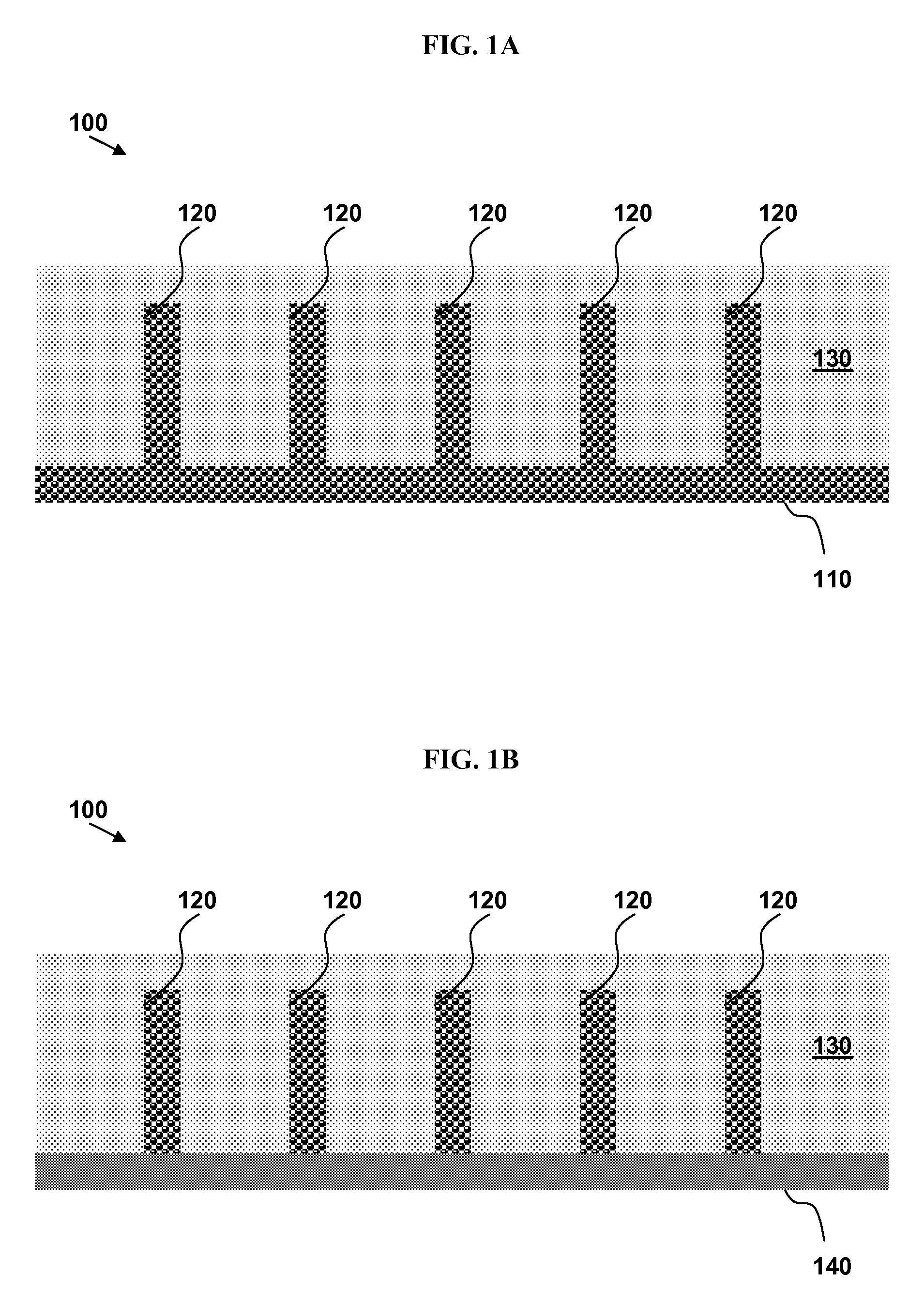
Three-dimensional electrodes with conductive foam for electron and lithium-ion transport
a technology of conductive foam and electron transport, which is applied in the direction of active material electrodes, non-aqueous electrolyte accumulator electrodes, cell components, etc., can solve the problems of low energy density of batteries, inability to achieve successful approaches, and inability to sustain the way of life. achieve the effect of high ionic conductivity and faster ra
- Summary
- Abstract
- Description
- Claims
- Application Information
AI Technical Summary
Benefits of technology
Problems solved by technology
Method used
Image

Examples
example 1a
Multiphysics Model of Electrode
[0114]A COMSOL Multiphysics® finite-element model is developed for a Li-ion battery with a three-dimensional electrode, comprising the conductive foam protrusions as described above. The model is based on a one-dimensional model described in Newman et al., J. Electrochem. Soc. 1996, 143, 1890. Electronic and ionic charge transport, material transport in electrolyte and electrodes, and Butler-Volmer electrode kinetics are included in the model.
[0115]The configuration and boundary conditions of the finite-element COMSOL model are shown in FIG. 3A. The model represents a two-dimensional slice of a structure made from parallel ridges of porous foam material (conductive porous ridges).
[0116]The electric potential distributions of a traditional planar electrode and the modeled three-dimensional electrode with conductive porous ridges are shown in FIG. 3B. According to FIG. 3B, there is a lower voltage drop across the three-dimensional electrode, which result...
example 1b
Optimization of Electrode
[0118]Using the model as constructed and described in Example 1, a series of simulations are carried out to calculate the energy density as a function of electrode geometry. It is found that the greatest increase in energy density occurs for foam pillars that are 300 μm in height and 20 μm in width, spaced 200 μm apart, within the parameter space explored.
example 2
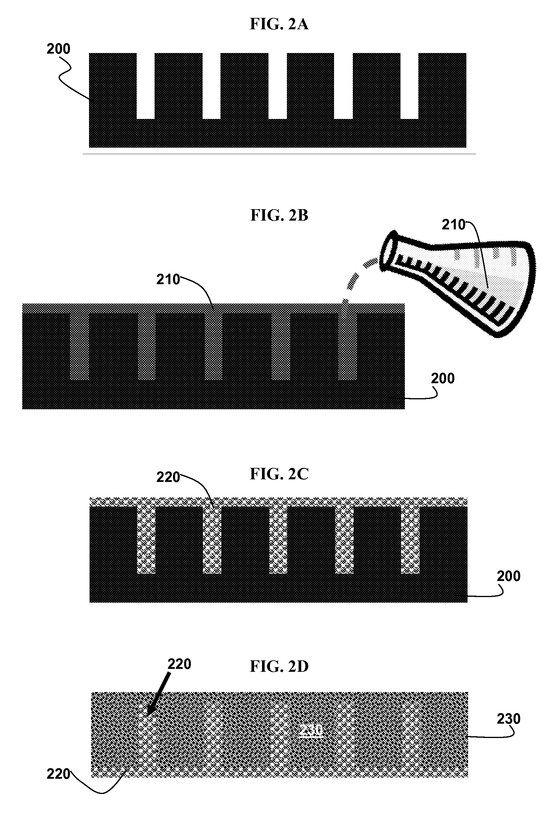
Formation of a Si Mold
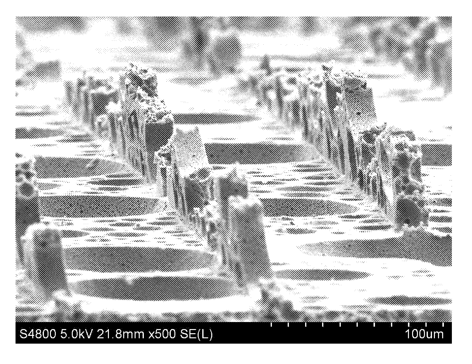
[0119]Guided by the model in Examples 1A and 1B, a mold is formed by creating a photomask with 25 μm wide lines spaced 200 μm apart. A Si wafer is coated with photoresist, exposed through the mask, and then the unexposed resist is washed away. Then the wafer is etched using a deep reactive ion etch (DRIE) to create an array of high-aspect-ratio silicon trenches spaced about 200 μm apart and about 250 μm deep. The trenches are about 18 μm wide after processing.
PUM
| Property | Measurement | Unit |
|---|---|---|
| width | aaaaa | aaaaa |
| height | aaaaa | aaaaa |
| pore-size | aaaaa | aaaaa |
Abstract
Description
Claims
Application Information