
Sound suppressor cooling system

a cooling system and sound suppressor technology, applied in the field of sound suppressors for firearms, can solve the problems of end users, structural damage, eventual failure, etc., and achieve the effect of increasing heat transfer and improving flow and cooling of the sound suppressor

Inactive Publication Date: 2015-03-03
CRONHELM PETER WILLIAM
View PDF7 Cites 41 Cited by
  • Summary
  • Abstract
  • Description
  • Claims
  • Application Information

AI Technical Summary

Benefits of technology

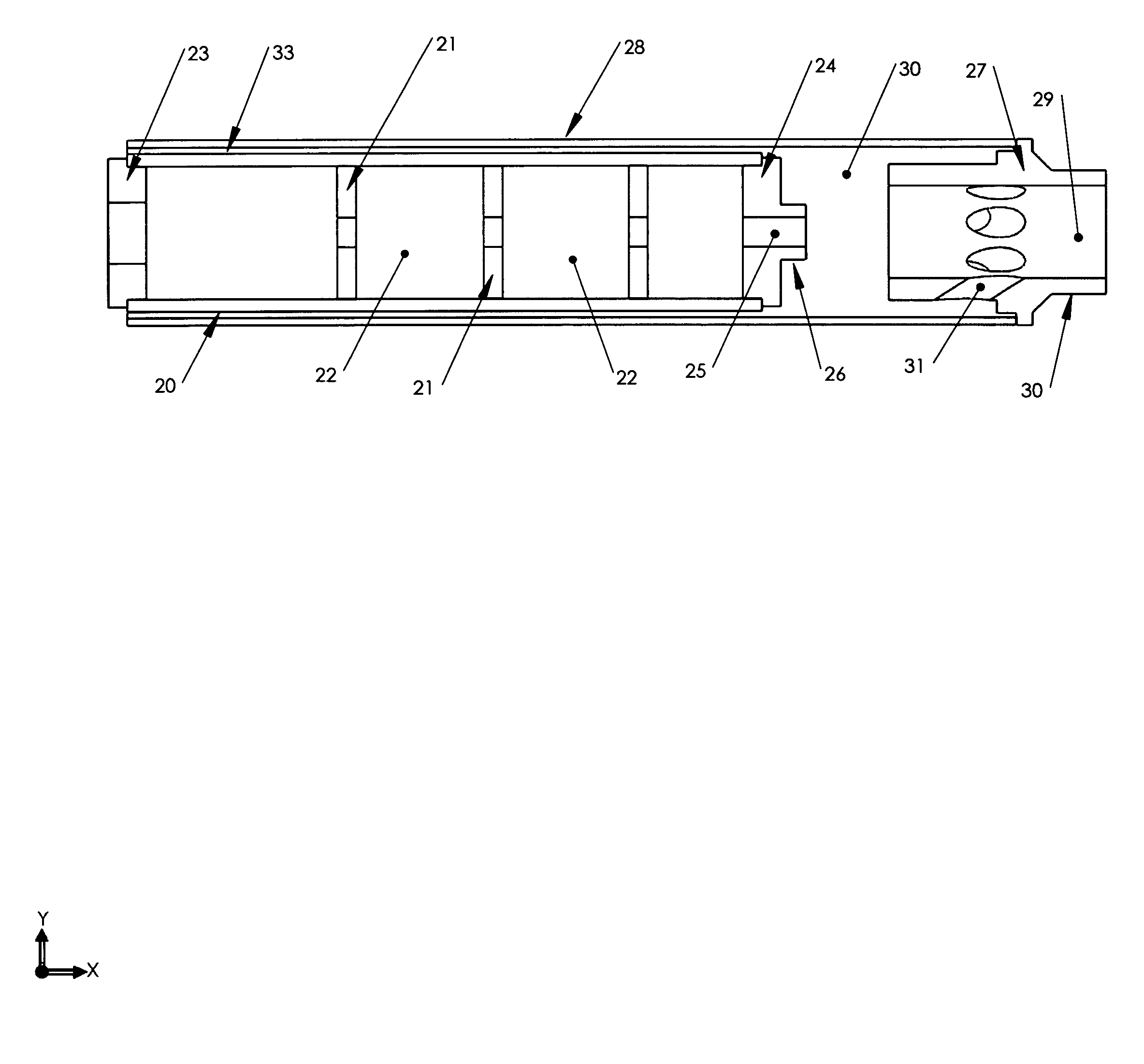
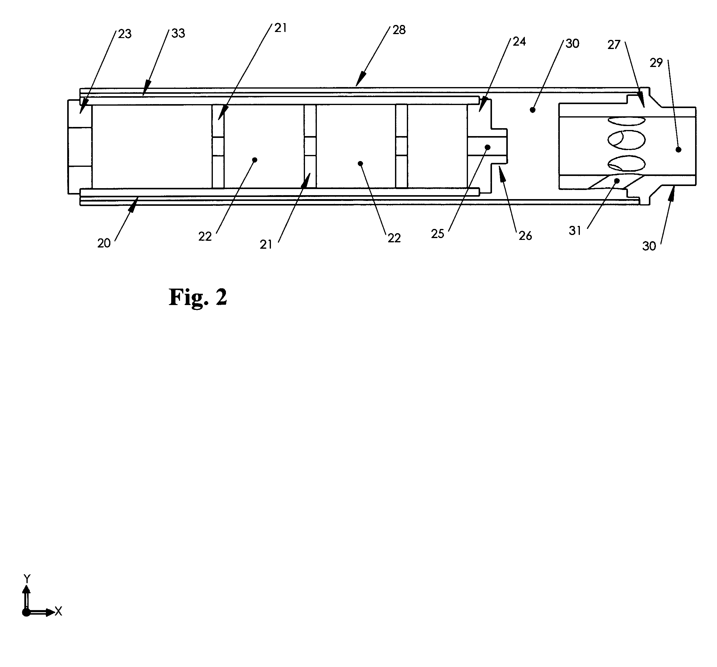
The present invention provides improvements to firearm sound suppressors by using a cooling system. The cooling system includes a suction structure and a shroud that fits over the sound suppressor. The suction structure has a convergent-divergent flow surface to enhance flow and cooling of the sound suppressor. The cooling system may also include vanes that increase cooling and improve mixing of the coolant and hot muzzle gases. The cooling system may be integrated with the sound suppressor or attached separately. The invention allows for improved cooling of the firearm sound suppressor and increased heat transfer from the sound suppressor to the cooling system.

Problems solved by technology

The temperature will also increase with the number of shots fired through the suppressor, and with the wide spread use of suppressed semi-automatic and automatic rifles, there are a number of problems that end users can face that are caused by the increase in temperature when firing occurs.
Prolonged firing will result in structural damage and eventual failure unless the sound suppressor is constructed from high-temperature resistant metals such as stainless steels or other steel alloys like austenitic nickel-chromium based super alloys such as Inconel™.
These materials have drawbacks and these include increased weight, problems with machining, and cost compared to other steel alloys.
Even using these materials, prolonged or extreme firing will eventually result in degradation of the structural integrity of the suppressor and failure of the suppressor itself.
The high temperatures from such extreme firing i.e. continuous automatic fire of 400 or more rounds can contribute to the eventual failure.
The continuous training schedules of anti-terrorist and military personnel means that suppressors used on their small arms are exposed to high round counts daily or weekly.
With the drawbacks of increased weight and cost, some manufacturers have resorted to standard engineering practices such as thinning out the structures while at the same time attempting to maintain structural integrity.
Some of these suppressors have been somewhat successful; others have not.
Even with such super alloys, extreme usage will eventually result in component failure and temperature is a major factor in the failure of sound suppressor components.
The retention of heat in the sound suppressor from multiple shots is a major problem with sound suppressors for use with short barreled automatic rifles, automatic rifles and machine guns.
The main problem with titanium when used with sound suppressors is that while the weight factor is ideal, the suppressors are not suitable for use with automatic small arms such as assault rifles and machineguns.
The main reason is that the heat from prolonged semi-auto or automatic fire results in eventual failure of the suppressor components in much the same manner as prolonged semi-automatic or automatic fire with stainless steel suppressors.
A temperature of approximately 800 degrees F. for the titanium suppressor will start to result in failure while a temperature of approximately 1200 degrees F. will start to result in the failure of the stainless steel suppressor.
While the reduced weight provides a large advantage, again it is prolonged semi-automatic or automatic firing that will eventually result in failure of the suppressor.
Another problem facing the users of sound suppressors, more so with suppressed sniper rifles, is that of heat mirage.
Heat mirage is optical distortion caused by heat waves rising directly from the sound suppressor in front of the telescopic sight.
After shooting in hot environments, this can cause the sniper to miss the target and this may be critical in military operations.

Method used


Image

  • Sound suppressor cooling system
  • Sound suppressor cooling system
  • Sound suppressor cooling system

Examples


Embodiment Construction

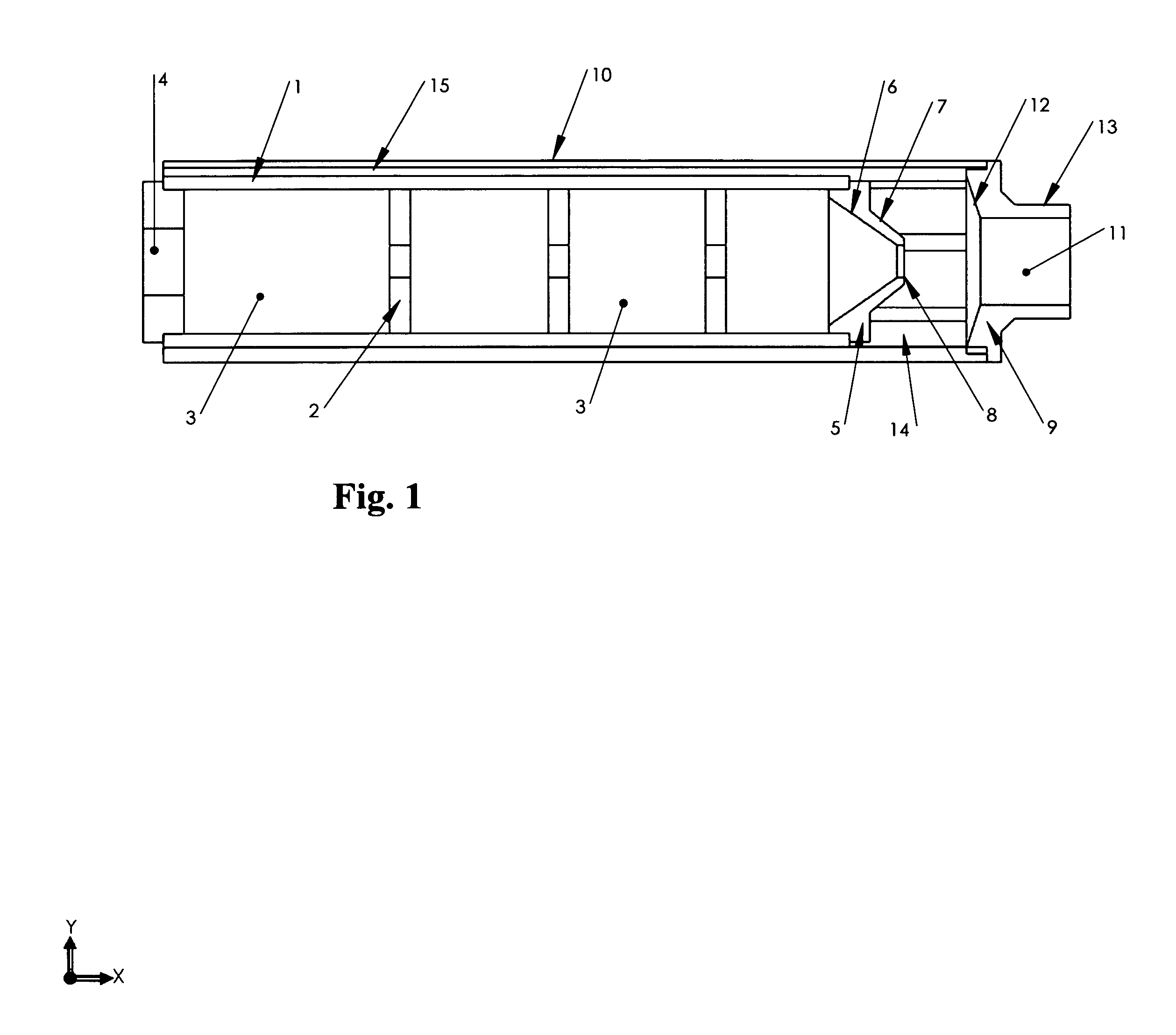
[0032]Referring to FIG. 1 showing a cross-sectional view of an embodiment of the present invention, illustrating a sound suppressor with baffles positioned along an interior of the suppressor housing, with a cooling system positioned at the distal end of the sound suppressor and a shroud positioned externally of the sound suppressor. The sound suppressor consists of a hollow cylindrical housing 1, with spaced baffle elements 2, creating a series of expansion chambers 3, between the baffles 2. At the proximal end of the suppressor is a rear end cap 4 and at the distal end of the suppressor an inner front end cap 5 and both of these end caps are secured to the housing 1 preferably by screw threads, by welding or other suitable securing means. The rear end cap 4 may be provided with threads for attachment to a host firearm or alternate attachment methods such as quick detach / connect systems may be used. The inner front end cap 5 has an internal convergent surface 6 and a partially conv...


PUM


Abstract

A firearm sound suppressor cooling system comprising a sound suppressor housing with means for reducing the pressure of gases exiting from a discharged firearm with a shroud that is attached to the exterior of the sound suppressor housing, an annular chamber formed between the sound suppressor housing and the shroud, and a nozzle positioned at the distal end of the sound suppressor and the shroud. The nozzle produces a suction effect upon discharge of the firearm and due to the suction effect, ambient air is aspirated through the annular chamber, and cools the firearm sound suppressor.

Description

CROSS REFERENCED TO RELATED APPLICATIONS[0001]This application claims the benefit of U.S. Provisional Patent Application No. 61 / 400,851, filed Aug. 4, 2010, which is incorporated by reference herein.BACKGROUND OF THE INVENTION[0002]1. Field of the Invention[0003]This application relates broadly to sound suppressors for firearms. More particularly, it concerns a cooling system for a firearm sound suppressor, and allows for the cooling of a firearm sound suppressor through the use of a cooling system attached to a firearm sound suppressor or being integral to a firearm sound suppressor.[0004]2. Description of the Prior Art[0005]Sound suppressors are intended to capture, cool and delay the exit of hot muzzle gases from a firearm. If the firearm sound suppressor is efficient in reduction of the discharge sound, the sound suppressor will experience an increase in temperature during firing as the longer the gases are retained within the suppressor, the higher the temperature of the suppre...

Claims


Application Information

Patent Timeline
IPC IPC(8): F41A21/30
CPCF41A21/30F41A13/00F41A13/10F41A21/24
Inventor CRONHELM, PETER WILLIAM
Owner CRONHELM PETER WILLIAM
Learn More