Method of and system for detecting skew between parallel signals

a parallel signal and detection method technology, applied in the field of parallel communication, can solve the problems of time difference between transmissions on multiplexed polarizations, transmission errors, transmission errors, etc., and achieve the effect of simple receiver structure and simple encoder structur

Active Publication Date: 2015-03-03
NEC CORP
View PDF11 Cites 48 Cited by
  • Summary
  • Abstract
  • Description
  • Claims
  • Application Information

AI Technical Summary

Benefits of technology

[0031]The object of the present invention is to provide a simple method to monitor the transmission skew between parallel signals generated from a serial signal, usable on wide skew ranges and without necessitating the information of upper layers, or the presence of a training pattern or prefix added to the transmitted data.
[0035]In another aspect of the invention, the period of the optical amplitude dip imprinted on the parallel signals is changed during the monitoring of the transmission skew, in order to improve the precision of the monitoring. The generated signal proportional to the skew is generated for different cases of period of the optical amplitude dip.
[0040]In the present invention, dips are inserted between a fixed number of symbols, but the time period of the symbols or the number of symbols to be transmitted within the network does not change. Therefore, when implementing the present invention, the transmitters and receivers can have the same bandwidth as the one necessary to carry the actual data, which is an improvement when compared to background art relying on overheard or training patterns. In addition, in the present invention, no constraint is added to the encoding of the data, which makes encoding more simple when compared to the use of overheads or training patterns. In the present invention, the skew monitoring does not required data to be decoded as with overheads or training patterns, therefore it is not directly sensible to errors within transmitted bits. The present invention compares electrical signals generated from the detected dips, therefore the measurable skew is finer than one bit or symbol period transmitted through the network. In the present invention, no constraint is added to the relation between the physical receiver and higher layer information. Skew monitoring is independent from higher layer information, which enable simpler receiver structures as compared to background art using FEC or upper layer information.

Problems solved by technology

However, polarization demultiplexing is required in order to recover each of the polarization multiplexed signals.
Differences between the streams are transmission errors.
Differences in electrical or optical path lengths for the considered bits results in time difference for the transmission on the multiplexed polarizations.
This problem is known as intra-channel skew.
This situation results in a change of the bit sequence during the transmission, i.e. in a transmission error.
Considering the fact that the optical components for each polarization paths are usually connected by spliced fiber, such a tolerance may be hard to achieve on production.
Moreover, Differential Group Delay (DGD) accumulated on the fiber during transmission may delay one polarization compared to the other one, and therefore randomly and dynamically change the intra-channel skew.
In addition, dynamic network reconfiguration or switching may cause a value of a link skew to change dynamically.
Therefore, correcting the delay between polarization-multiplexed signals with this method is likely to require several attempts before finding the adequate delay compensation, complicating the practical implementation.
Moreover, continuous control of the delay between polarized signals is not implementable with this method.
Finally, using this method requires to use the information of upper layer of the network to control physical layer parameters, which may complicate system design or hinder interoperability.
This approach requires training patterns, which are susceptible to decrease the amount of transmitted data at constant bit rate.
With higher bit rate, the symbol period decreases, therefore the skew problem becomes critical.
Therefore the skew problem becomes critical with higher bit rates.
This increases the cost and complexity of receivers and can cause a degradation of the performance of the receiver.
When errors appear due to noise or degradation of the signal transmitted through the network, this can affect read PING and PONG patterns, and therefore cause an error in the skew evaluation.
As a consequence, this can have a tremendous impact on the serialized signal that FEC or other correction method may not be able to compensate.
This increases the cost and complexity of receivers and may cause a degradation of the performance of the receiver.
In cases where errors appear due to noise or degradation of the signal transmitted through the network, this can affect the reading of I(n) patterns, and therefore cause an error in the skew evaluation.
As a consequence, this can have a tremendous impact on the serialized signal that FEC or other correction method may not be able to compensate.
This increases the cost and complexity of receivers and may cause a degradation of the performance of the receiver.
Such requirement increases the complexity of the receiver.
This may have a negative impact on the stability of the integrity of the received data when distortions appear on the transmission path.

Method used


Image

  • Method of and system for detecting skew between parallel signals
  • Method of and system for detecting skew between parallel signals
  • Method of and system for detecting skew between parallel signals

Examples


Embodiment Construction

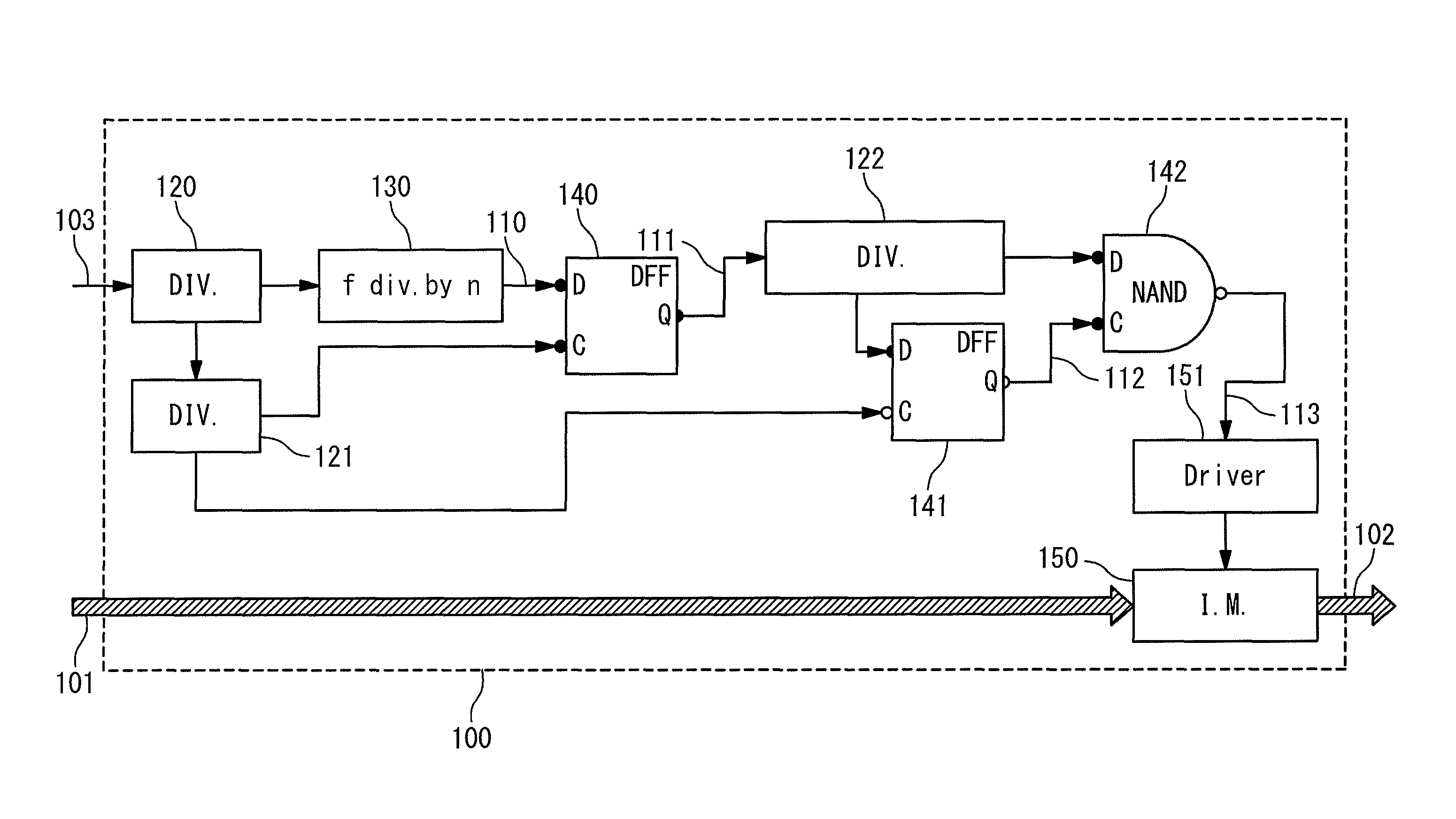
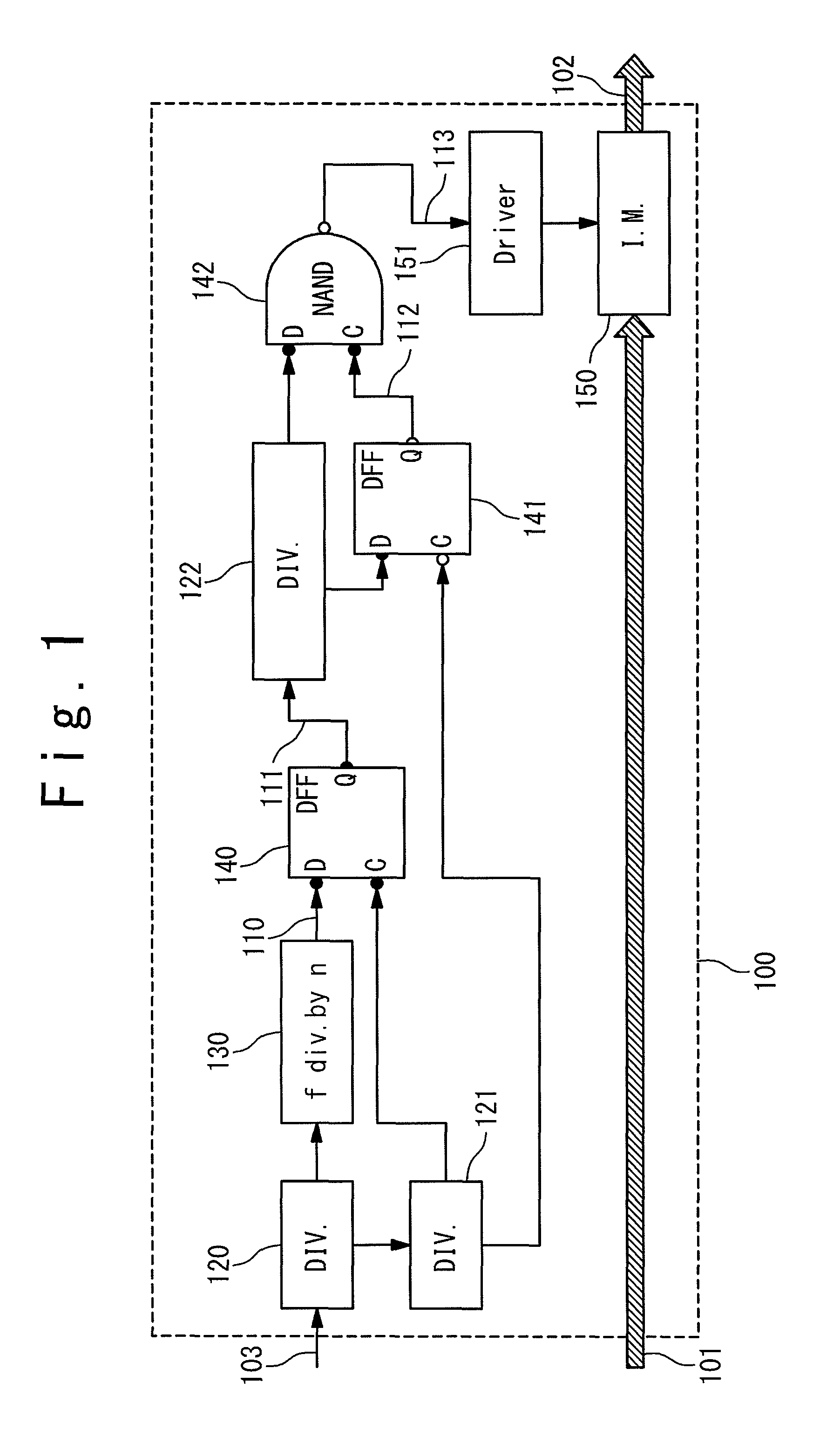
[0055]FIG. 1 is a block diagram schematically showing a configuration of an apparatus, which can be used in order to imprint a dip on the optical amplitude of a light signal. Before explaining in detail the apparatus of FIG. 1, the Pseudo-Return-to-Zero format of index n (P-RZ(n)) is defined in analogy to Return-to-Zero (RZ) and Non-Return-to-Zero (NRZ) formats. In RZ format, the optical amplitude returns to zero between two consecutive symbols. In NRZ format, the optical amplitude does not return to zero between consecutive symbols, and it is forced to zero if and only if the symbol amplitude is zero or crosses zero. In P-RZ(n) format, the amplitude returns to zero between consecutive symbols every n symbols and does not return to zero in the other cases, unless the symbol amplitude is zero or crosses zero. P-RZ(n) format is not a RZ format of at an n time slower clock frequency, as the amplitude is forced to zero and is relaxed at a very steep slope (same slope as RZ). P-RZ(n) cau...


PUM


Abstract

A method is provided for detecting the skew between parallel light signals generated from a serial data stream. The method can be used with polarization multiplexed signal, as well as with wavelength division multiplexed signals, spatial division multiplexed signals, phase modulated signals, or intensity modulated signals. The method can be used with direct detection schemes as well as with coherent detection schemes. The method is provided with: imprinting dips between a fixed number of transmitted symbols of the parallel signals; detecting an electrical signal related to the dips for each parallel signal; and comparing the electrical signals in delay.

Description

CROSS REFERENCE TO RELATED APPLICATION[0001]This application is a National Stage of International Application No. PCT / JP2009 / 058036 filed on Apr. 16, 2009, the contents of all of which are incorporated herein by reference in their entirety.TECHNICAL FIELD[0002]The present invention relates generally to an optical communication technique, and more particularly to parallel communications, in which one signal at a high bit rate is split and transmitted through parallel channels at lower bit rates, and is reconfigured from the transmitted parallel channels.BACKGROUND ART[0003]Through Serial to Parallel conversion, a serial high bit rate channel is split into lower bit rate channels, in order to transmit them as parallel channels between a same transmission start point to a same transmission stop point, while the parallel channels do not have any crosstalk ideally. The parallel channels are then serialized into a high bit rate channel, which contains the transmitted information of the or...

Claims


Application Information

Patent Timeline
Patent Type & Authority Patents(United States)
IPC IPC(8): H04J3/00H04B10/077H04J3/06H04J14/02H04J14/04H04L7/00H04L25/14
CPCH04B10/0775H04L25/14H04J14/04H04J14/02H04L7/0075H04J3/0658
Inventor LE TAILLANDIER DE GABORY, EMMANUELFUKUCHI, KIYOSHI
Owner NEC CORP
Why Eureka
Try Eureka