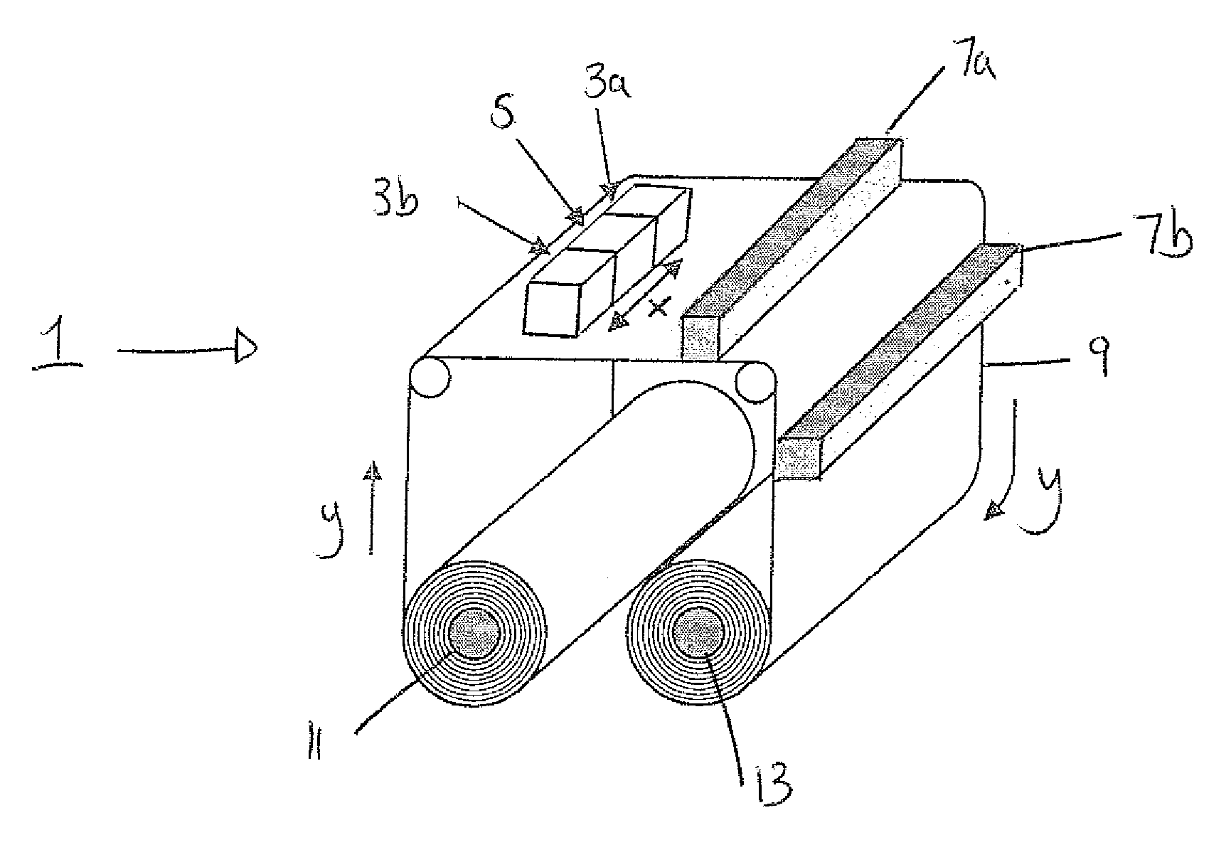
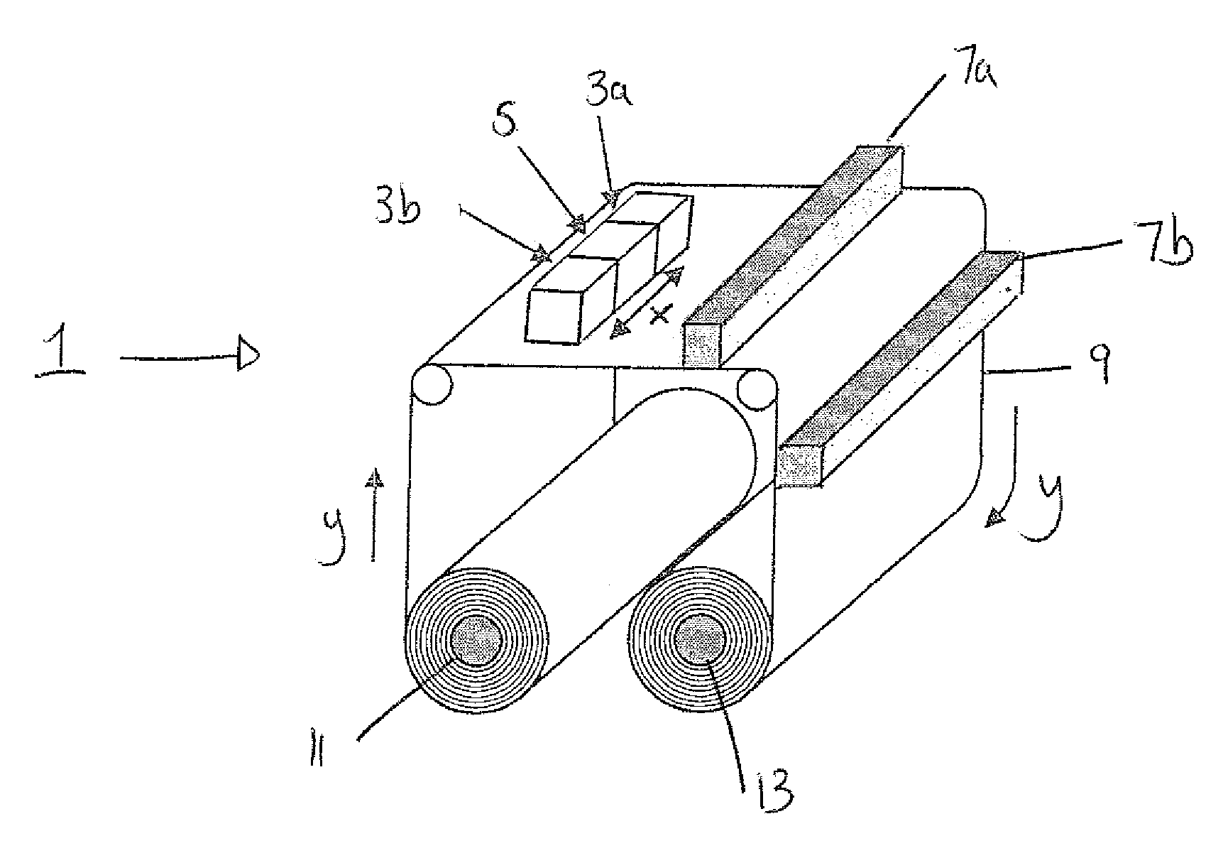
Printing method

a printing method and printing technology, applied in the field of printing ink, can solve the problems of the substrate “setting” and the tacky surface of the film, and achieve the effects of good surface cure, good surface cure, and good adhesion to the substra

Active Publication Date: 2015-03-10
SERICOL GROUP
View PDF17 Cites 4 Cited by
  • Summary
  • Abstract
  • Description
  • Claims
  • Application Information

AI Technical Summary

Benefits of technology

[0020]The combination of a first, partial cure step using an LED source and a second curing step using a flash lamp (e.g. xenon or krypton) surprisingly allows control of the print image (i.e. matt, satin or gloss) while providing good adhesion to the substrate and good surface cure. Furthermore, the method does not require a nitrogen environment in order to achieve a good surface cure. The method of the present invention is also more reliable and has lower power consumption than methods that use mercury discharge lamps, for example.
[0021]Without wishing to be bound by theory, it is believed that exposure to the LED source causes partial curing of ink below the surface of the printed film, which causes the ink to “set” on the substrate. This step is also known as “pinning”. The LED source produces radiation that is capable of penetrating into the ink. Thus, partial cure of the ink throughout the printed film can be achieved. Control of the print image can be achieved by varying the power of the UV radiation from the LED source in order to provide a matt, satin or gloss effect and / or to improve the colour gamut. This primary curing step therefore defines the image quality. However, the surface of the film remains tacky after partial curing, due to the inhibiting effect of oxygen in the atmosphere adjacent to the printed ink surface. A second curing step comprising exposure to UV radiation emitted from a flash lamp has been found to provide excellent surface cure. The high peak irradiance of the flash lamp overcomes the inhibiting effect of oxygen at the ink surface since it results in a high level of radical formation despite the short duration (i.e. low dose). In contrast, the LED has a lower peak irradiance but the exposure time is longer leading to a high dose which-permeates through the ink. The overall effect is a particularly good complementarity between the two radiation source leading to a combination of excellent surface and through cure.
[0024]UV dose is the total energy provided to a surface per unit area and is measured in mJ / cm2. The UV dose provided to the ink during the partial cure step is preferably 10 to 300 mJ / cm2, more preferably 50 to 250 mJ / cm2 and most preferably 75 to 200 mJ / cm2. These doses are lower than those required for full curing. The UV dose per unit area can be controlled by varying the radiant power of the LED source and / or by varying the length of time that the ink is exposed to the radiation. Preferably, the LED source emits at reduced power, for example, 90% or less, preferably 65% or less and most preferably 50% or less of the maximum power output. When the LED emits at reduced power, the cooling requirements are reduced, which means that the printer design is less complex.

Problems solved by technology

Without wishing to be bound by theory, it is believed that exposure to the LED source causes partial curing of ink below the surface of the printed film, which causes the ink to “set” on the substrate.
However, the surface of the film remains tacky after partial curing, due to the inhibiting effect of oxygen in the atmosphere adjacent to the printed ink surface.

Method used


Image

  • Printing method
  • Printing method

Examples


example 1

[0092]Cyan, yellow, magenta and black ink-jet ink formulations having the following compositions were prepared by mixing the components in the given amounts (percentages are given by weight and are based on the total weight of the ink).

[0093]

TABLE 1ComponentsCyanYellowMagentaBlack2 Phenoxy ethyl acrylate43.9443.0242.4343.6N-vinyl caprolactam24.5923.3426.9924.75Ethoxylated(3) trimethylol propane7.497.216.957.42tracrylateUV stabilizer ST10.30.40.20.3Propoxylated neopentyl glycol4.08.0—3.0diacrylateSartomer CN964 A854.04.0——(urethane acrylate oligomer)Sartomer PRO 20169———6.6(urethane acrylate oligomer)Cyan pigment dispersion8.65———Yellow pigment dispersion—7.0——Magenta pigment dispersion——16.40—Black pigment dispersion———6.3Irgacure 8194.04.04.04.0Irgacure 29592.02.02.02.0Isopropyl thioxanthone1.01.01.02.0Byk 307 (surfactant)0.030.030.030.03

[0094]Evaluation

[0095]The inks were drawn down on to 220 micron gloss PVC substrate using a no. 2 Kbar, depositing a 12 micron wet film. The ink f...

example 2

[0098]Table 3 shows the composition of the black ink provided in Example 1, and a second black ink in which the photoinitiator system has been changed (percentages are given by weight and are based on the total weight of the ink).

[0099]

TABLE 3ComponentsBlack Example 1Black Example 22 Phenoxy ethyl acrylate43.644.6N Vinyl caprolactam24.7524.75Ethoxylated(3) trimethylol7.427.42propane tracrylateUV stabilizer ST10.30.3Propoxylated neopentyl3.03.0glycol acrylateSartomer PRO 201696.66.6Black pigment dispersion6.36.3Irgacure 8194.04.0Irgacure 29592.02.0Isopropyl thioxanthone2.0—Irgacure 369—1.0Byk 3070.030.03

[0100]The inks were drawn down on to 220 micron gloss PVC using a no 2 Kbar (12 micron). The cure was assessed on a conveyorised drier fitted with one 80 W / cm medium pressure mercury lamp. The UV dose required to achieve through cure and surface cure was noted. The degree of surface cure was assessed by pressing the surface of the ink with a finger and through cure was assessed by scr...


PUM

PropertyMeasurementUnit
wavelength distributionaaaaaaaaaa

Abstract

The present invention provides a method comprising: applying a UV-curable ink to a substrate; partially curing the ink by exposing the ink to UV radiation from an LED source; and exposing the partially cured ink to UV radiation from a flash lamp. The flash lamp is a xenon or krypton flash lamp. An apparatus for performing the method and an ink adapted for use in the method are also provided.

Description

FIELD OF THE INVENTION[0001]This invention relates to a method of printing ink and in particular to a method of printing UV-curable ink. The invention also relates to a printing apparatus and inks adapted for use in the method of the invention.BACKGROUND OF THE INVENTION[0002]In ink-jet printing, minute droplets of black or coloured ink are ejected in a controlled manner from one or more reservoirs or printing heads through narrow nozzles on to a substrate, which is moving relative to the reservoirs. The ejected ink forms an image on the substrate. For high-speed printing, the inks must flow rapidly from the printing heads, and to ensure that this happens they must have a low viscosity at the jetting stage. The ink viscosity is typically below 25 mPas at jetting temperature.[0003]One type of ink contains unsaturated organic monomers or oligomers that polymerise by irradiation, commonly with UV light, in the presence of a photoinitiator. This type of ink has the advantage that it is ...

Claims


Application Information

Patent Timeline
Patent Type & Authority Patents(United States)
IPC IPC(8): C09D11/101B41J11/00B41M5/00B41M7/00
CPCC09D11/101B41J11/002B41M7/0081B41M5/0047B41M5/0064B41J11/00214
Inventor GOULD, NIGELMCGREGOR, BARRY MICHAEL
Owner SERICOL GROUP
Why Eureka
Try Eureka