
Selective catalytic reduction catalyst system

a catalytic reduction and catalyst technology, applied in the direction of metal/metal-oxide/metal-hydroxide catalysts, machines/engines, arsenic compounds, etc., can solve the problem of difficult to achieve effective abatement of no/sub>x/sub>from lean burn engines, the activity of many metal-promoted zeolites, such as cu and fe versions of zsm-5 and beta, and the effect of increasing the steady sta

Active Publication Date: 2015-04-28
BASF CORP
View PDF27 Cites 25 Cited by
  • Summary
  • Abstract
  • Description
  • Claims
  • Application Information

AI Technical Summary

Benefits of technology

The patent text describes a selective catalytic reduction (SCR) catalyst system that includes two different catalyst compositions. The first composition has a different composition than the second composition, and both compositions are placed on a common substrate. This allows for better control of the SCR process and improved performance of the catalyst system in reducing nitrogen oxides (NOx) emissions from exhaust gases. The first and second catalyst compositions can be modified by changing their composition, structure, or metal exchange, and can be selected from a variety of molecular sieves and metal oxides. The system can also be modified by adding or removing a layer of the first or second catalyst composition. Overall, the patent text provides a flexible and effective solution for reducing NOx emissions from exhaust gases.

Problems solved by technology

From the standpoint of emissions, however, diesel engines present problems more severe than their spark-ignition counterparts.
Effective abatement of NOx from lean burn engines is difficult to achieve because high NOx conversion rates typically require reductant-rich conditions.
Unfortunately, it has been found that under harsh hydrothermal conditions, such as reduction of NOx from gas exhaust at temperatures exceeding 500° C., the activity of many metal-promoted zeolites, such as Cu and Fe versions of ZSM-5 and Beta, begins to decline.
This decline in activity is believed to be due to destabilization of the zeolite such as by dealumination and consequent loss of metal-containing catalytic sites within the zeolite.
Additionally, certain existing catalysts, such as copper promoted zeolites (e.g Cu-SSZ-13), tend to produce unacceptably high N2O emissions.

Method used


Image

  • Selective catalytic reduction catalyst system
  • Selective catalytic reduction catalyst system
  • Selective catalytic reduction catalyst system

Examples


example 1

Preparation of Catalyst Materials

[0132]Vanadia-Titania Catalyst

[0133]A standard vanadia / titania / tungsten (V2O5 (2.5%) / WO3 (10%) / TiO2) catalyst was prepared and a slurry was made at about 30-40% solids by milling to provide a washcoat slurry.

[0134]Cu-Zeolite

[0135]A CuCHA (SSZ-13) powder catalyst was prepared by mixing 100 g of Na-form CHA, having a silica / alumina mole ratio of 30, with 400 mL of a copper (II) acetate solution of about 1.0 M. The pH was adjusted to about 3.5 with nitric acid. An ion-exchange reaction between the Na-form CHA and the copper ions was carried out by agitating the slurry at about 80° C. for about 1 hour. The resulting mixture was then filtered to provide a filter cake, and the filter cake was washed with deionized water in three portions until the filtrate was clear and colorless, and the washed sample was dried.

[0136]The obtained CuCHA catalyst comprised CuO at a range of about 2.5 to 3.5% by weight, as determined by ICP analysis. A CuCHA slurry was prepa...

example 2

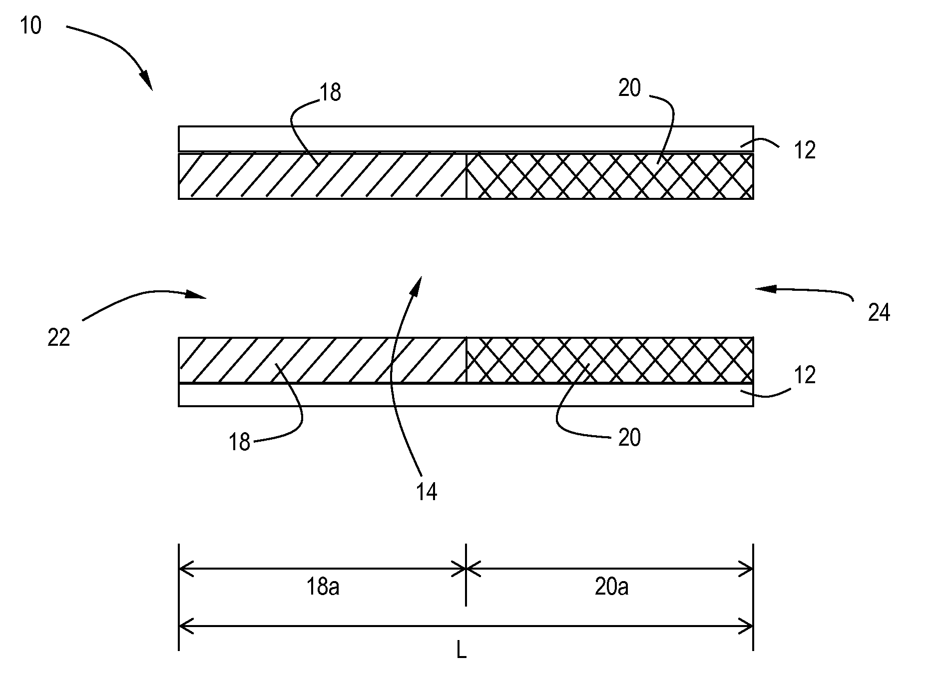
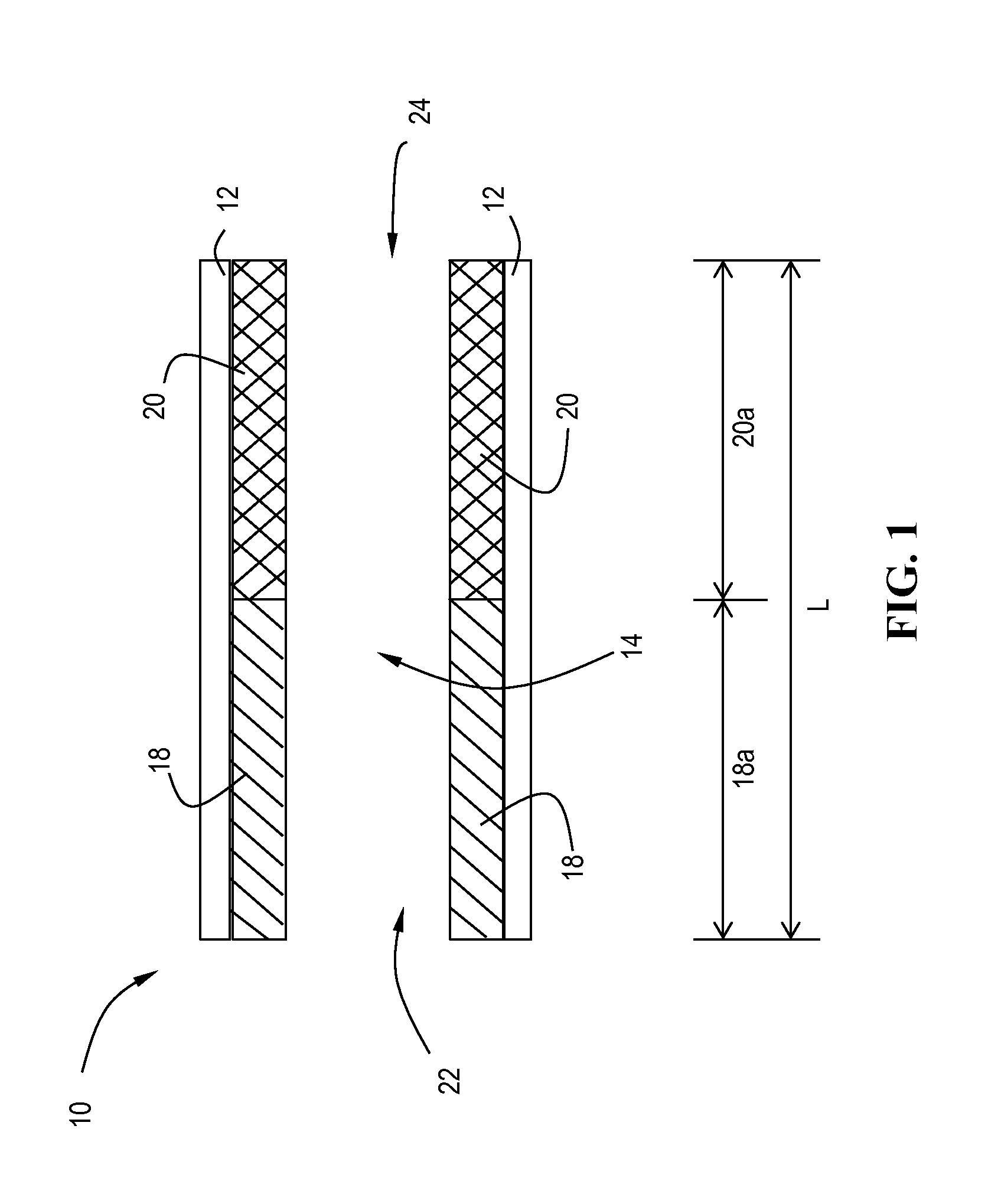
Catalyst System Laterally Zoned

[0137]The slurries described above were separately coated onto 12″D×6″L cellular ceramic substrate having a cell density of 400 cpsi (cells per square inch) and a wall thickness of 4 mil. The coated substrates were dried at 110° C. for 3 hours and calcined at about 400° C. for 1 hour. The coating process was repeated once to obtain a target washcoat loading of in the range of 3 g / in3 on the vanadia-titania coated core, and 2.1 g / in3 on the CuCHA coated core. The samples were aged for 200 hours at 550° C. on a heavy duty diesel engine test cell.

example 4

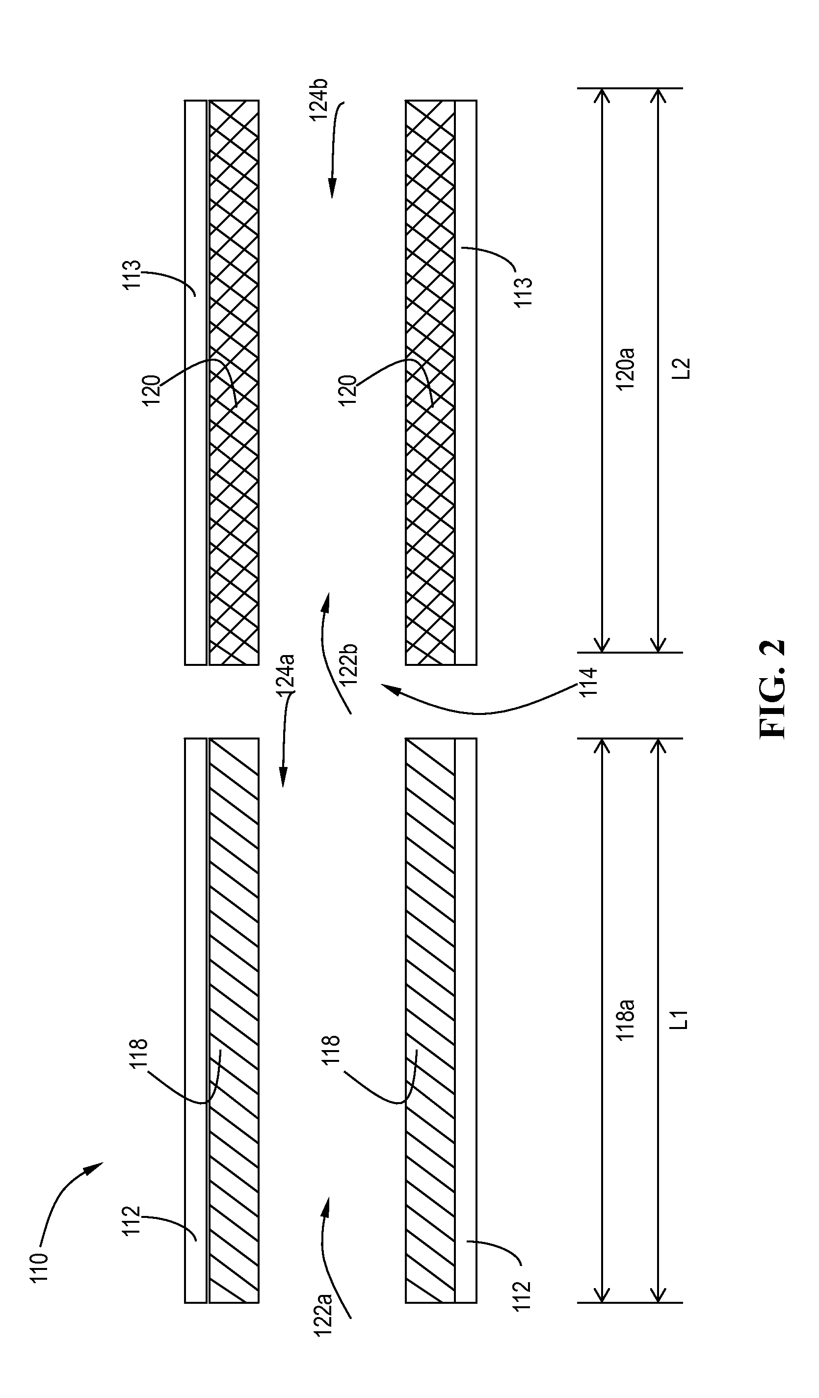
Engine Testing of Laterally Zoned Systems

[0139]The catalyst systems in Example 3 and 4 were tested out on a 9 L heavy duty engine together with a motoring electric dynamometer. The test bench is capable of running both steady-state and transient test cycles. In the current work, both a Heavy duty transient test cycle (HDTP) and a non-road transient test cycle (NRTC) were run. Catalysts samples were full size 12″ diameters parts (400 / 4), which were 200 h-550° C. engine aged prior to evaluations. To demonstrate the advantage of the lateral zoned system of a 12″×6″ V-SCR brick upstream of a 12″×6″ Cu-CHA brick, a reference sequential 12″×6″ Cu+12″×6″ Cu SCR system was also evaluated. In such a comparative study, only the first SCR catalyst brick were switched between V-SCR and Cu-SCR, other systems such as the second SCR brick, urea injection system, sample probing locations were kept the same.

[0140]During evaluation tests, two MKS FTIR samplers were positioned at SCR upstream and down...


PUM

PropertyMeasurementUnit
temperaturesaaaaaaaaaa
temperatureaaaaaaaaaa

Abstract

Described are SCR catalyst systems comprising a first SCR catalyst composition and a second SCR catalyst composition arranged in the system, the first SCR catalyst composition promoting higher N2 formation and lower N2O formation than the second SCR catalyst composition, and the second SCR catalyst composition having a different composition than the first SCR catalyst composition, the second SCR catalyst composition promoting lower N2 formation and higher N2O formation than the first SCR catalyst composition. The SCR catalyst systems are useful in methods and systems to catalyze the reduction of nitrogen oxides in the presence of a reductant.

Description

CROSS-REFERENCE TO RELATED APPLICATIONS[0001]This application claims the benefit of priority under 35 U.S.C. §119(e) to U.S. Provisional Patent Application No. 61 / 781,760, filed on Mar. 14, 2013, which is hereby incorporated by reference in its entirety.TECHNICAL FIELD[0002]The present invention pertains to the field of selective catalytic reduction catalysts. More particularly, embodiments of the invention relate to selective catalytic reduction catalyst systems comprising a first SCR catalyst composition and a second SCR catalyst composition, a lean burn engine exhaust system, and methods of using these catalyst systems in a variety of processes such as abating pollutants in exhaust gases.BACKGROUND[0003]Operation of lean burn engines, e.g. diesel engines and lean burn gasoline engines, provide the user with excellent fuel economy and have very low emissions of gas phase hydrocarbons and carbon monoxide due to their operation at high air / fuel ratios under fuel lean conditions. Die...

Claims


Application Information

Patent Timeline
Patent Type & Authority Patents(United States)
IPC IPC(8): B01D53/94F01N3/10B01J23/745B01J29/06B01J23/30B01J23/22B01J21/06F01N3/24B01J23/00B01J29/072B01J29/70B01J29/76F01N3/20
CPCB01D53/9431B01J21/063B01J23/22B01J23/30B01D53/9404B01J29/061B01J29/072B01J29/7015B01J29/763F01N3/10F01N3/2066B01D53/9418B01D2255/9022B01D2255/9032F01N2510/0682F01N2510/0684F01N2570/18B01D2255/2047B01D2255/2065B01D2255/20707B01D2255/20715B01D2255/20723B01D2255/20738B01D2255/20761B01D2255/20776B01D2255/2092B01D2255/40B01D2255/50B01D2255/911Y10S502/52712Y10S502/52713Y02C20/10B01J37/0244B01J21/04B01J21/066B01J23/02B01J23/10B01J23/72B01J23/745B01J29/72B01J37/0036Y02T10/12B01J35/19
Inventor TANG, WEIYONGMOHANAN, JAYA L.
Owner BASF CORP
Features
  • Generate Ideas
  • Intellectual Property
  • Life Sciences
  • Materials
  • Tech Scout
  • Unparalleled Data Quality
  • Higher Quality Content
  • 60% Fewer Hallucinations
Learn More