
Oxygen sensor for internal monitoring of tissue oxygen in vivo

a tissue oxygen and oxygen sensor technology, applied in the field of improvement, can solve the problems of affecting the life of patients, affecting the quality of life of patients, affecting the quality of life of patients,

Active Publication Date: 2015-06-02
THE TRUSTEES OF THE UNIV OF PENNSYLVANIA
View PDF22 Cites 3 Cited by
  • Summary
  • Abstract
  • Description
  • Claims
  • Application Information

AI Technical Summary

Benefits of technology

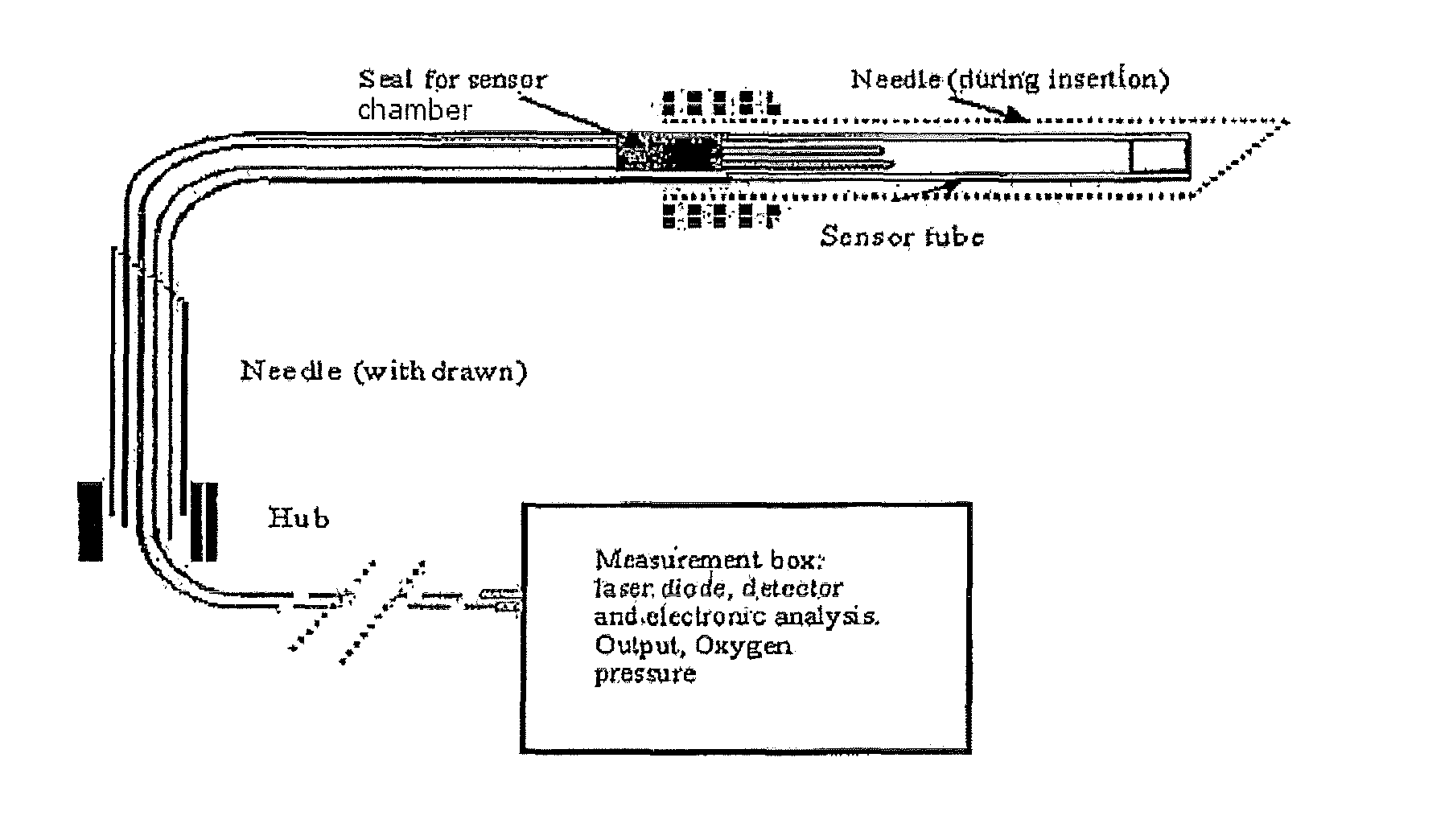
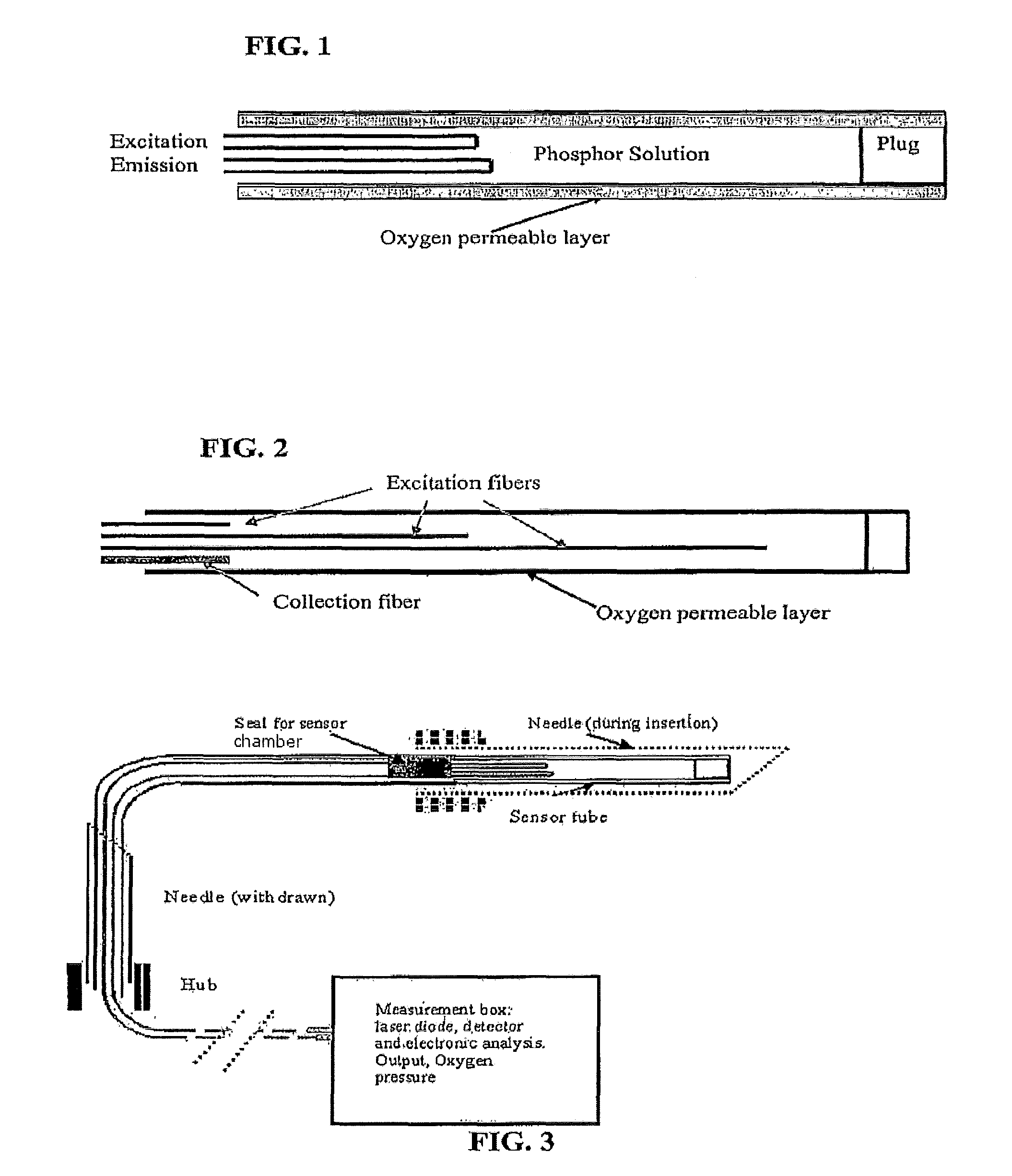
[0015]The unique design and placement within the tissue, particularly effective within muscle tissue, permits the oxygen probe to be rapidly inserted in a matter of seconds, even under difficult conditions, such as those often faced by first medical responders. Once in place, the probe provides immediate data regarding cardiac and pulmonary function (tissue oxygen) to facilitate rapid and accurate treatment of the patient.
[0017]It is a further object of the invention to provide a tissue probe for use in the system as described, which is effectively used directly in the tissue of a patient without requiring the protection and limitations of insertion into the patient via a blood vessel. In one aspect of the invention, the probe comprises an oxygen-quenchable phosphorescence emitting compound (hereinafter “phosphor,” also referred to herein as the “analyte”) dissolved in solution in an aqueous solvent within the sensor chamber. In contrast to the prior art in this area, when a probe is used in a vein or artery, it must be less 200-300 μm in diameter to permit passage into the lumen of the vessel, whereas the present invention is not so limited, providing distinct advantages over intravascular prior art devices.
[0021]Further, in accordance with the invention, light-emitting diodes are used for excitation of the phosphorescence, thereby taking advantage of their ability to provide a bright monochromatic light source which can easily be modulated at the required frequency and with the desired waveform.

Problems solved by technology

For example, in traumatic injury, the primary threat to life is often the loss of blood and the resulting hemorrhagic shock and hypotension, under-perfusion of tissue and abnormal the blood flow among and within the tissues.
As a result, regions of tissue become hypoxic, or relatively devoid of oxygen.
However, while the prior art probes are intended for measuring “tissue oxygen” in a patient in vivo, they require insertion into the lumen of a blood vessel and actually measure blood gases, not oxygen in the tissue surrounding the vessel.
Nor can the prior art systems be effective in regions not supplied with large vessels, such as muscle tissue, or in damaged tissue areas where the blood vessels are no longer intact, as in emergency situations.
One structural problem with the prior art sensing systems of the type described for use in blood vessels, is that the structure of the chambers and probe configuration often encourage the formation of blood clots or thrombi.
Furthermore, the complexity and difficulty of manufacturing multi-fiber probes is well known, due to the small diameters of the fibers and requirements of their arrangement.
Such probes must be small enough to fit within a blood vessel while still permitting blood to flow, especially problematic for neonatal or pediatric applications in which the patient's veins or arteries may be too small in diameter for insertion of the probe assembly.
The prior art tissue oxygen or multianalyte sensors have failed to effectively deal with the problems set forth above, and none offer a method for measuring oxygen in tissue other than via a blood vessel.
For example, if prior art probes were inserted directly into tissue, rather than into a blood vessel, they would collapse or be disabled under the pressure of the surrounding tissue.
They lack sufficient wall strength to withstand tissue pressure without the protection of a blood vessel and a surrounding fluid environment.
Consequently, without the protection by the blood and blood vessel, insertion of a prior art probe directly into a non-fluid, tissue environment could compress and damage the sensor chamber, resulting in failure or a significantly decreased excitation of a phosphor sensor, as well as decreased collection of the returned phosphorescent excitation light.

Method used


Image

  • Oxygen sensor for internal monitoring of tissue oxygen in vivo
  • Oxygen sensor for internal monitoring of tissue oxygen in vivo
  • Oxygen sensor for internal monitoring of tissue oxygen in vivo

Examples


example 1

Monitoring of an Ischemic Bowel

[0100]Pediatric and adult patients can develop conditions, such as volvulus, necrotizing enterocolitis and strangulation of the intestine due to an adhesion. These cause regional ischemia of the intestine requiring an exploratory laparotomy and possible resection. Often there are areas of the intestine that are transition zones with potential viability. To help preserve as much of the intestine as possible a second (or third) surgical look may be required to assess these areas. Further, there is no way to judge the outcome of therapies to improve intestinal viability until it is reassessed visually. Computerized tomography is of limited use and usually cannot distinguish viable from non-viable tissue, except at the irreversible extreme. Plain X-rays are also only useful at the extreme, when perforation has occurred due to tissue necrosis.

[0101]Solution Using Present Invention:

[0102]Following the initial laparotomy, the surgeon can, in accordance with t...

example 2

Monitoring of a Muscle Flap

[0103]As part of restorative surgery to fill in a space created by re-section of diseased tissue or loss from trauma, surgeons often mobilize muscle from one area and transfer it to another. This muscle may still have its native vascular supply intact, or it may be completely disconnected, in which case it is reattached to another vascular supply (free flap). Such surgery is often complicated by flap failure due to an inadequate vascular supply, and unfortunately, it is often difficult to monitor the integrity of the flap because it is subcutaneous. Doppler ultrasound may be used, but it can only determine whether a pulse can be detected in or near the tissue.

[0104]Solution Using the Present Invention:

[0105]An oximeter catheter of the present invention could be inserted along the body of the flap or inserted into the body of the muscle, and the integrity of the muscle can then be monitored at various points on the flap while in situ. This could be easily r...

example 3

Monitoring Cardiopulmonary Resuscitation

[0106]The American Heart Association has established guidelines for providing cardiopulmonary resuscitation (CPR) to victims of cardiac or respiratory arrest. One of the difficulties in providing this potentially life saving care, is the inability to monitor in real time, the adequacy of chest compressions and the delivery of oxygen into the tissues of the patient. In an intensive care unit a patient may have an arterial line already established, permitting medical practitioners to periodically sample the patient's blood to monitor progress. However, before the patient reaches the ICU, arterial lines are not used because they take time and expertise to establish, making them impractical to use in an acute situation. As a result critical measurements of tissue oxygen are not possible.

[0107]Solution Using the Present Invention:

[0108]At initiation of CPR, one could insert the oximeter catheter into a deltoid, masseter or other muscle as a surroga...


PUM


Abstract

Provided is a durable oxygen sensitive probe of sufficient strength to withstand direct tissue pressures in vivo, the probe comprising a sensor chamber within a biocompatible, gas-permeable membrane containing an oxygen sensitive analyte solution producing oxygen quenchable phosphorescence when excited. Further provided is a tissue oxygen detection and measurement system comprising the probe, and methods for use of the probe and the system to directly, rapidly and accurately measure tissue oxygen levels in a patient without reliance on blood vessels or fluid protection of the probe.

Description

REFERENCE TO RELATED APPLICATIONS[0001]This patent application claims priority to Provisional Application 60 / 756,112, filed Jan. 4, 2006 and PCT Application PCT / US2007 / 000292, filed Jan. 4, 2007, which is herein incorporated in its entirety.FIELD OF THE INVENTION[0002]The present invention provides an improved system for measuring tissue oxygen partial pressure (concentration). Further provided is an improved optical probe for directly using this system to measure tissue oxygen of a patient without requiring delivery of the sensor to the lumen of a blood vessel.BACKGROUND OF THE INVENTION[0003]The present invention is based upon the phenomenon that oxygen has a quenching effect on the molecular luminescence of various chemical compounds and that this effect can be employed for imaging oxygen concentrations (partial pressure) in vivo. Animals, especially mammals, are dependent upon having adequate oxygen supplies in their body tissues. In mammals, the circulatory system employs speci...

Claims


Application Information

Patent Timeline
Patent Type & Authority Patents(United States)
IPC IPC(8): A61B5/1459A61B5/00A61B5/145A61B5/1455G02B6/032
CPCA61B5/14542A61B5/0059A61B5/1455A61B5/14551A61B5/14552A61B5/6846G02B6/032A61B5/14539A61B5/1459G02B2006/0325
Inventor WILSON, DAVID F.SCHEARS, GREGORY J.
Owner THE TRUSTEES OF THE UNIV OF PENNSYLVANIA
Learn More