Method for producing wiring harness, and wiring harness

a technology of wiring harnesses and wire harnesses, which is applied in the direction of insulated conductors, cables, conductors, etc., can solve the problems of exposed portion of the conductors that includes the splices being vulnerable to corrosion, and achieve excellent water resistance, high air tightness, and high air tightness

Inactive Publication Date: 2015-06-09
AUTONETWORKS TECH LTD +2
View PDF26 Cites 8 Cited by
  • Summary
  • Abstract
  • Description
  • Claims
  • Application Information

AI Technical Summary

Benefits of technology

[0036]The method for producing the wiring harness of the present invention can provide a wiring harness that includes a sealing member that has higher airtightness because a spot in the sealing member that light does not reach and accordingly cannot be photocured can be cured by redox copolymerization.
[0037]Having higher airtightness, the wiring harness of the present invention has especially excellent water resistance.

Problems solved by technology

An exposed portion of the conductors that includes the splice is vulnerable to corrosion due to electrical leakage or contact of water if left as it is.

Method used


Image

  • Method for producing wiring harness, and wiring harness
  • Method for producing wiring harness, and wiring harness
  • Method for producing wiring harness, and wiring harness

Examples


first preferred embodiment

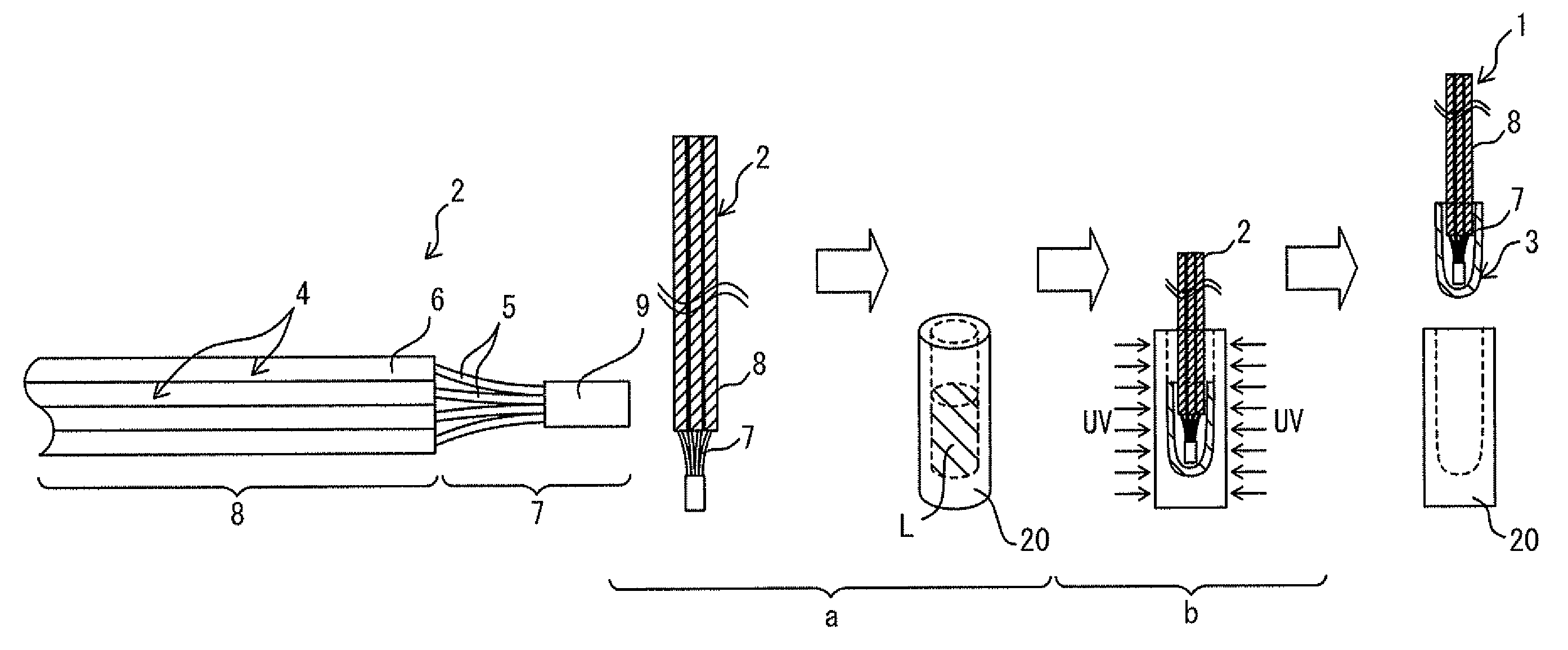
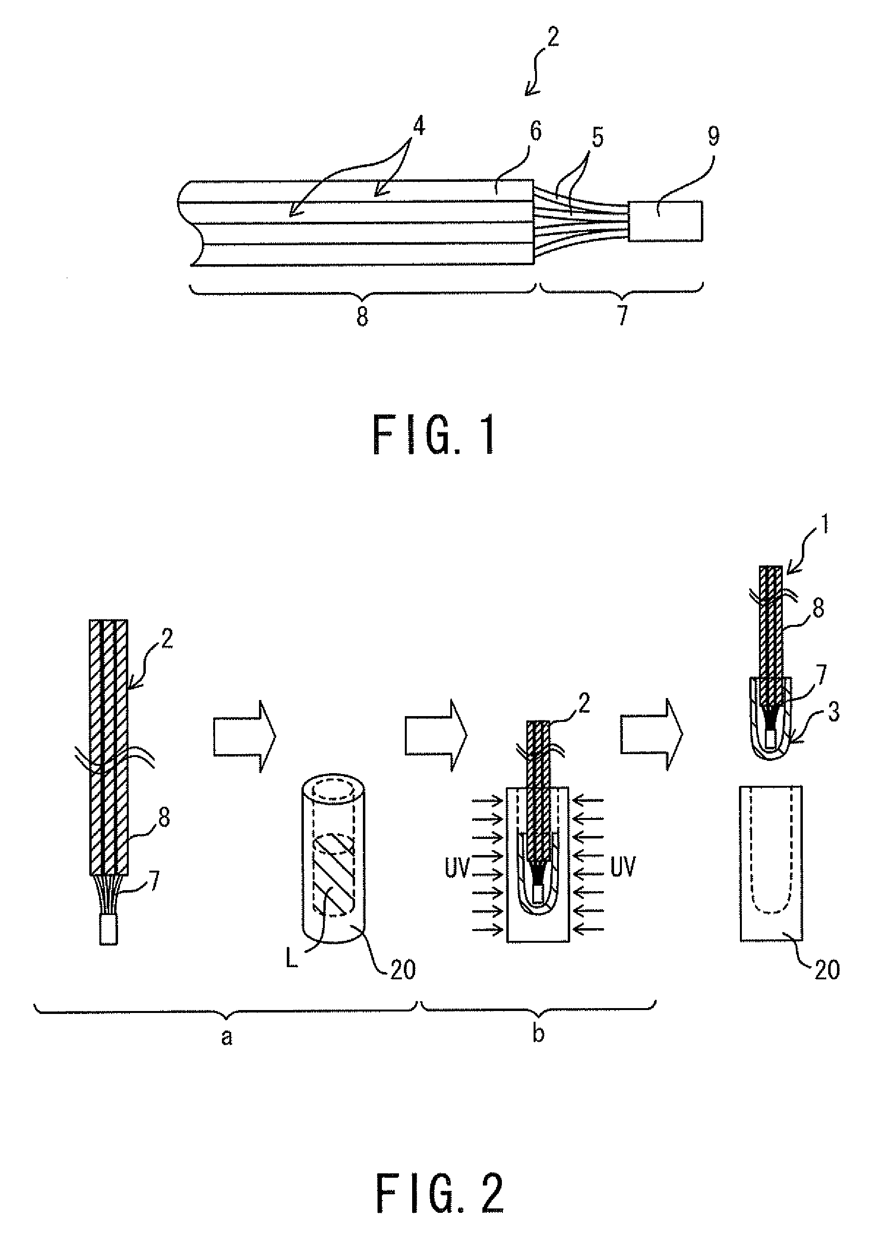
[0054]In the method for producing the wiring harness of the present embodiment, the wiring harness is produced by forming a sealing member on a bunch of electric wires. First, a description of the bunch of electric wires on which the sealing member is formed is provided.

[0055]FIG. 1 is a view showing a schematic configuration of a bunch of electric wires. A bunch of electric wires 2 consists of a bunch of insulated electric wires 4 as shown in FIG. 1. Known electric wires can be used as the electric wires 4 as appropriate. Each of the insulated electric wires 4 includes a conductor 5 having a linear shape, and an insulation 6 with which the conductor 5 is coated. The conductors 5 are made from a conductive material such as copper, and the insulations 6 are made from an insulating material such as polyvinyl chloride.

[0056]The conductors 5 are not coated with the insulations 6 and are exposed at end portions of the insulated electric wires 4 of the bunch of the electric wires 2. That ...

second preferred embodiment

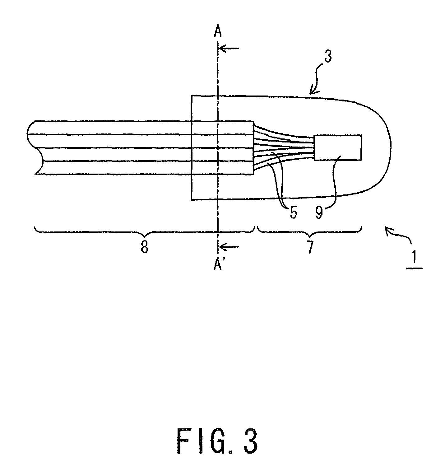
[0111]The method for producing the wiring harness of the second preferred embodiment differs in the shape of the bunch of electric wires 12 to which the sealing member 3 is provided. The bunch of electric wires 12 includes the splice 9 at its intermediate portion. FIG. 5 is a view showing a schematic configuration of the bunch of electric wires 12 including the splice 9 at its intermediate portion.

[0112]The conductors 5 are not coated with the insulations 6 and are exposed at the intermediate portions of the insulated electric wires 4 of the bunch of electric wires 12 as shown in FIG. 5. That is, the insulations 6 are formed on the conductors 5 such that the conductors 5 are exposed at their intermediate portions. The splice 9 is formed by connecting the conductors 5 at the exposed intermediate portions. The exposed bunched portion 7 is interposed by the two coated bunched portions 8 in the bunch of electric wires 12.

[0113]The exposed conductors 5 of the insulated electric wires 4 a...

example 1

[0124]

[0125]First, a solution A and a solution B that were necessary to prepare the composition solution was prepared under composition conditions as below. The density of the solution A was almost equal to that of the solution B.

[0126](Solution A)

[0127]2,4,6-trimethyl benzoil diphenyl phosphine oxide (photo polymerization initiator) [manuf.: BASF, LUCIRIN TPO], 2 parts by mass

[0128]Bis-(2,6-dimethoxybenzoyl)-2,4,4-trimethylpentylphosphine oxide (photo polymerization initiator) [manuf.: CIBA SPECIALTY CHEMICALS INC., IRGACURE 184], 1 part by mass

[0129]Cumene hydroperoxide (thermal radical polymerization initiator) [manuf.: KAYAKUAKUZO CO., LTD., KAYAKUMEN], 1 part by mass

[0130]Urethane acrylate oligomer (polymerizable compound) [manuf.: JSR CORPORATION], 40 parts by mass

[0131]Acrylate monomer (chain polymerizable compound), 50 parts by mass

[0132]Iso-bornyl acrylate monomer (cyclic polymerizable compound) [manuf.: NIPPON SHOKUBAI CO., LTD.], 15 parts by mass

[0133]Thiol compound (adhe...


PUM

PropertyMeasurementUnit
adhesion propertyaaaaaaaaaa
Young's moduliaaaaaaaaaa
viscosityaaaaaaaaaa

Abstract

A method for producing a wiring harness including a sealing member having higher airtightness includes a coat formation step of forming a coat by applying a composition solution that contains at least a photo polymerization initiator, a thermal radical polymerization initiator, a redox catalyst and a polymerizable compound to an exposed bunched portion and a coated bunched portion that is adjacent to the exposed bunched portion of the bunch of electric wires, and a light irradiation step of irradiating the coat formed on the exposed bunched portion and the adjacent coated bunched portion with light to photocure the coat.

Description

TECHNICAL FIELD[0001]The present invention relates to a method for producing a wiring harness in which a splice is sealed with a resin in order to prevent water immersion.BACKGROUND ART[0002]Conventionally, wiring harnesses are used for wiring in an automobile. Each of these wiring harnesses is made up of a bunch of electric wires including conductors that are coated with insulations, and includes a splice that is arranged to electrically connect the electric wires. The splice is formed by connecting the conductors by welding, soldering or crimping, which are exposed by peeling the insulations of the electric wires.[0003]An exposed portion of the conductors that includes the splice is vulnerable to corrosion due to electrical leakage or contact of water if left as it is. For this reason, a sealing member that is made from a resin is formed on the splice in order to prevent electrical leakage and water immersion.[0004]The conductors are bunched having narrow spaces left among them at...

Claims


Application Information

Patent Timeline
Patent Type & Authority Patents(United States)
IPC IPC(8): H01R9/05H01R4/72H01R4/22H01B7/282B29C35/08
CPCH01R4/72H01R4/22H01B7/2825B29C35/0805B29C2035/0827B29C35/0888
Inventor KAKUTA, TATSUYAHOSOKAWA, TAKEHIROSOHMA, KAZUYUKIHATTORI, TOMOYUKI
Owner AUTONETWORKS TECH LTD
Why Eureka
Try Eureka