Microchannel plate having a main body, image intensifier, ion detector, and inspection device

a microchannel plate and main body technology, applied in the field of microchannel plates, can solve the problems of reducing affecting the stability of the mcp production, and the manufacture of the mcp itself, so as to improve the temperature characteristic of the electric improve the acid resistance of the mcp, and increase the content of lead

a microchannel plate and main body technology, applied in the field of microchannel plates, can solve the problems of reducing affecting the stability of the mcp production, and the manufacture of the mcp itself, so as to improve the temperature characteristic of the electric improve the acid resistance of the mcp, and increase the content of lead

US9117640B2Active Publication Date: 2015-08-25HAMAMATSU PHOTONICS KK

Image

  • Microchannel plate having a main body, image intensifier, ion detector, and inspection device
  • Microchannel plate having a main body, image intensifier, ion detector, and inspection device
  • Microchannel plate having a main body, image intensifier, ion detector, and inspection device

Examples


Embodiment Construction

[0042]Each of embodiments of the microchannel plate (MCP) according to the present invention will be described below in detail with reference to the accompanying drawings. In the description of the drawings, the same portions or the same elements will be denoted by the same reference signs, without redundant description.

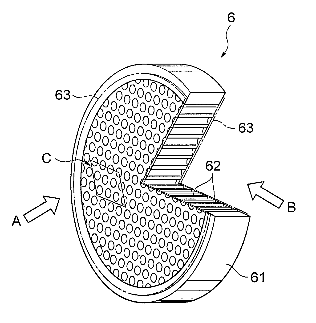
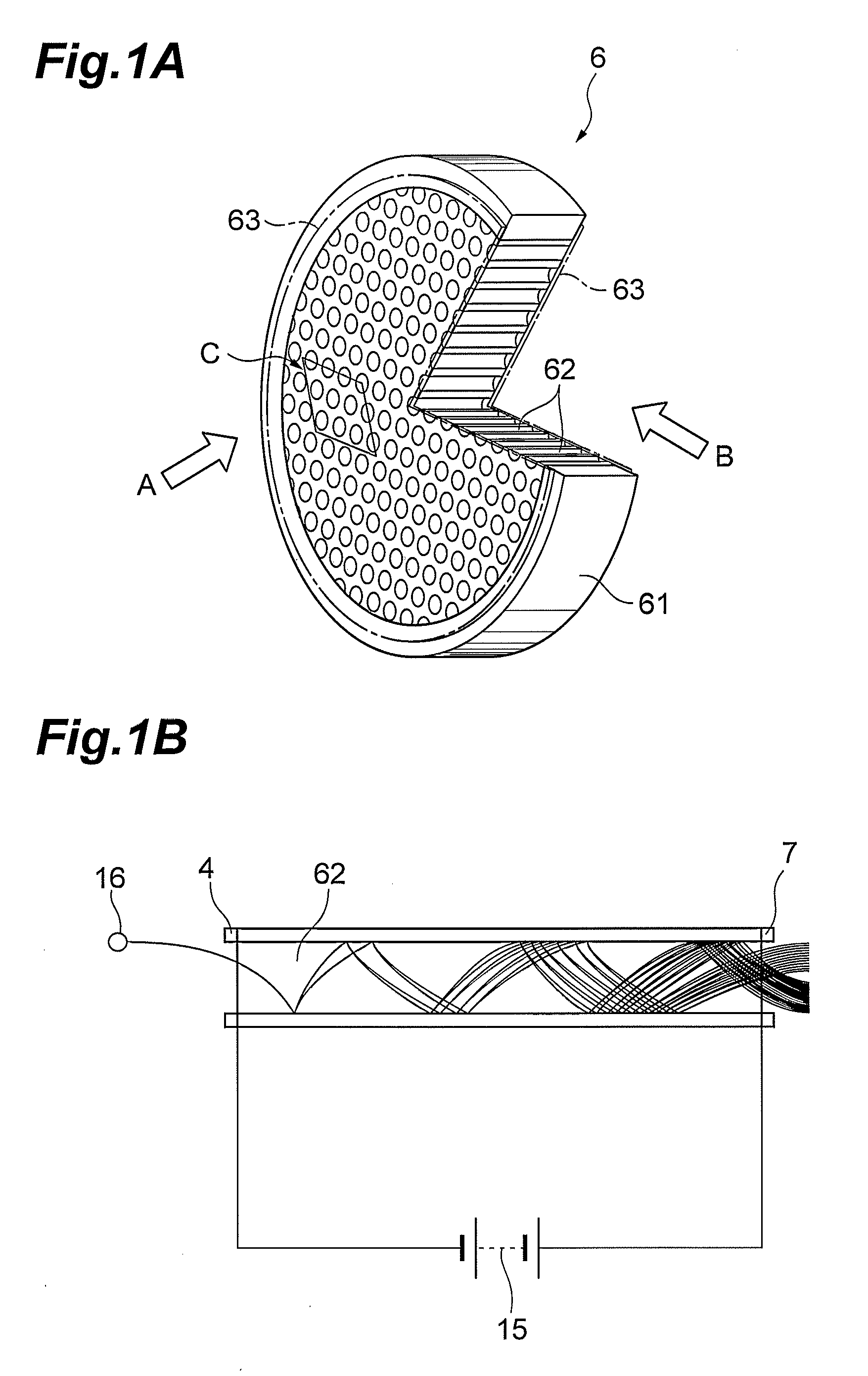
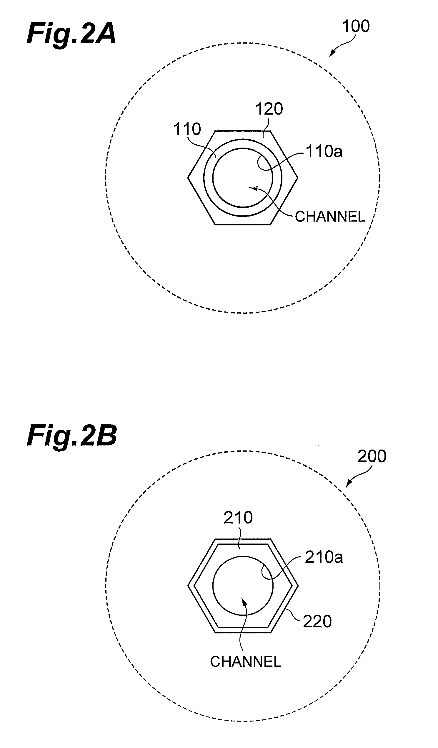
[0043]FIGS. 2A and 2B are drawings for explaining structures near a channel in MCPs according to the present embodiment. FIGS. 3A and 3B are drawings showing planar structures of the MCPs according to the present embodiment, which correspond to the part of the MCP (region indicated by arrow C) as viewed from the direction indicated by arrow A in FIG. 1A.

[0044]The MCPs according to the present embodiment are electron multipliers having the main body comprised of lead glass which exhibits electric insulation before a reduction treatment and exhibits electric conduction after the reduction treatment, and their basic structure resembles the structure of the MCP 6 shown i...


PUM


Abstract

The present invention relates to a low-resistance MCP with an expanded dynamic range and excellent environment resistance, in comparison with the conventional technology. The MCP has a double structure composed of hollow first cladding glasses whose inner wall surfaces function as channel walls, and a second cladding glass having a resistivity lower than that of the first cladding glasses.

Description

[0001]This application claims the benefit of U.S. Provisional Application No. 61 / 648,756 filed May 18, 2012, which is incorporated by reference herein in its entirety.BACKGROUND OF THE INVENTION[0002]1. Field of the Invention[0003]The present invention relates to a microchannel plate (which will be referred to hereinafter as MCP) used in an image intensifier, an ion detector, and inspection equipment including the ion detector, e.g., such as a mass spectrometer, a photoelectron spectrometer, an electron microscope, or a photomultiplier tube.[0004]2. Related Background Art[0005]A microchannel plate (MCP) has a plate-like structural body (main body) and is known as an electron multiplier in which a plurality of channels are regularly arranged. FIG. 1A is a partly broken drawing showing a structure of a typical MCP (single cladding structure) and FIG. 1B is a drawing for explaining an example of use of the MCP.[0006]More specifically, the conventional MCP 6 is a thin disk-shaped struct...

Claims


Application Information

Patent Timeline
25 Aug 2015
Publication
US9117640B2
IPC
H01J43/04; H01J43/24
CPC
H01J43/04; H01J43/246
Inventors
UCHIYAMA, TOSHIYUKI; HAYASE, YUSUKE