Interconnect for battery packs

a battery pack and interconnection technology, applied in the direction of laminating printed circuit boards, cell components, semiconductor/solid-state device details, etc., can solve the problems of loss of electrical connections, high cost of plates to manufacture and connect to battery terminals, circuits are generally limited to low-current applications, etc., to improve flexibility of a portion

Active Publication Date: 2015-09-29
CELLINK
View PDF47 Cites 78 Cited by
  • Summary
  • Abstract
  • Description
  • Claims
  • Application Information

AI Technical Summary

Benefits of technology

[0023]In some embodiments, the first insulating layer includes multiple slits. The multiple slits overlap with the continuous conductive channel and improve flexibility of a portion the first insulating layer positioned with the boundary of the slits. In some

Problems solved by technology
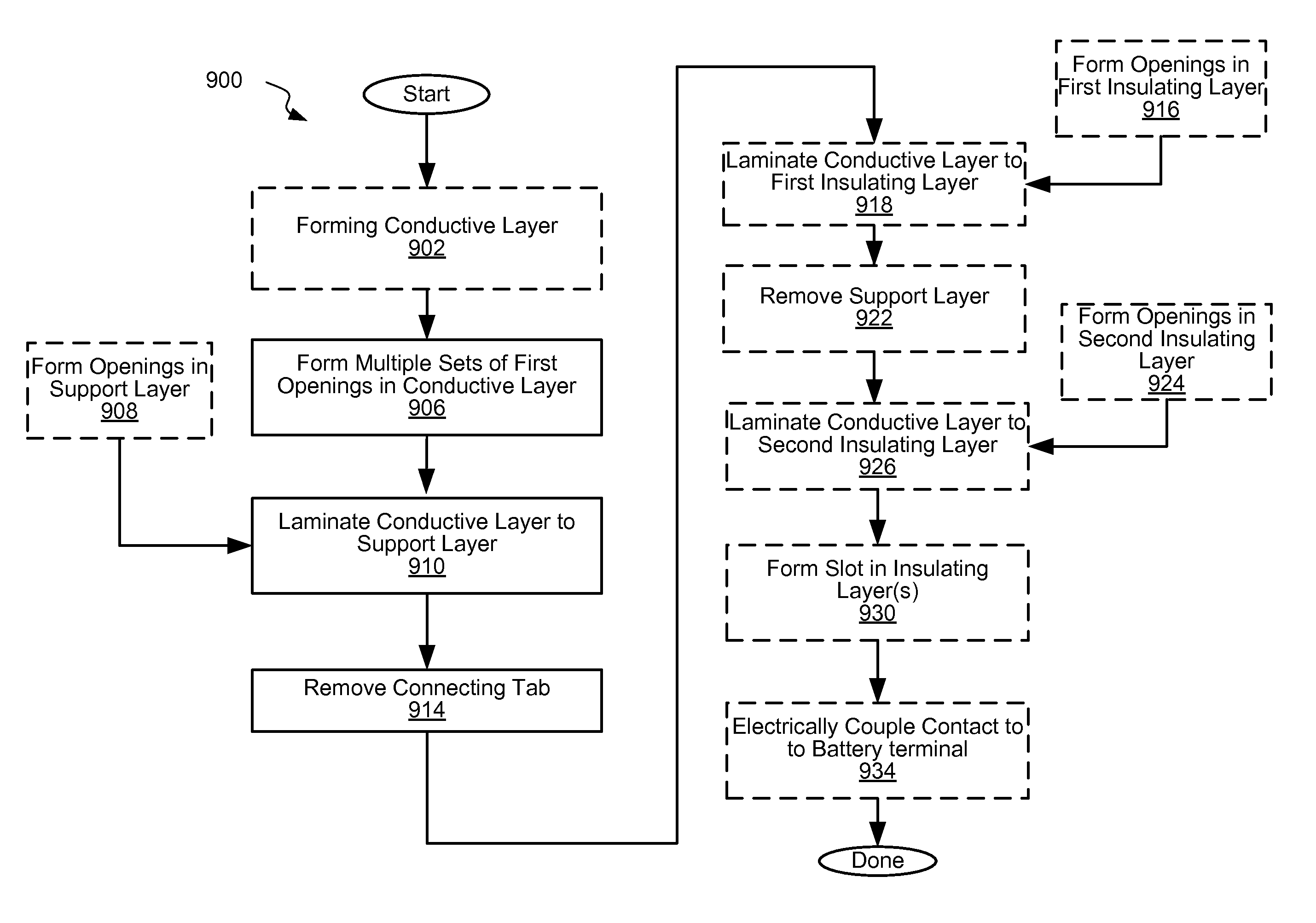
While these plates can transmit large currents and can be used for mechanical support, these plates are expensive to manufacture and connect to the battery terminals.
Furthermore, the rigidity may often interfere with relative motion between the cells and plates, potentially resulting in the loss of electrical connections.
However, such circuits are generally limited to low current applications.
Specifically, the thickness of conductive elements is limited by mask-and-etch capabilities, which are generally not suitable for high aspect ratio features and thick layers.
Furthermore, the prolonged etching required for thicker layer drives up the production cost of the flex circuit.
In addition, the extra thickness required for high currents makes it difficult to form fuses or fusible links with a controlled cross-sectional area.
When forming a fusible link by etching a thick conductive layer, it may be difficult to mask and etch a controlled narrow trace.
For example, a 140 micron thick conductive layer may be used to form traces (fusible links) that are at least 560-700 microns wide, which may be excessive for some applications.
This distortions may occur during fabrication of the interconnect circuit, during connection of the interconnect circuit to the battery cells, and during operation of the battery pack.
Without protection, exposed surfaces of aluminum tend to form a native oxide, which is insulating.
This in turn may reduce the conductivity at the interface of the two sublayers and potentially cause a loss of mechanical adhesion.
As compared to a small-area contact, this may reduce the contact resistance and provide greater electrical contact redundancy.
The use of traditional flexible circuits for interconnecting battery cells has a number of challenges.
The cross-sectional area of conductive components or, more specifically, the thickness of conductive layers suitable for maintaining low power losses is often so large that many conventional mask-and-etch techniques used to pattern these layers are prohibitively expensive and inefficient.
The disposal and/or treatment of this waste presents a significant environmental cha

Method used


Image

  • Interconnect for battery packs
  • Interconnect for battery packs
  • Interconnect for battery packs

Examples


Embodiment Construction

[0074]The ensuing detailed description of embodiments of this disclosure will be better understood when read in conjunction with the appended drawings. As used herein, an element or step recited in the singular and proceeded with the word “a” or “an” should be understood as not excluding plural of said elements or steps, unless such exclusion is explicitly stated. Furthermore, references to “one embodiment” are not intended to be interpreted as excluding the existence of additional embodiments that also incorporate the recited features. Moreover, unless explicitly stated to the contrary, embodiments “comprising” or “having” an element or a plurality of elements having a particular property may include additional elements not having that property.

INTRODUCTION

[0075]Many modern battery packs includes many cells that need to be interconnected and connected to terminals of a battery pack. For example, the Model S manufactured by Tesla Corporation in Palo Alto, Calif. has thousands of 186...


PUM

PropertyMeasurementUnit
Flow rateaaaaaaaaaa
Electrical conductoraaaaaaaaaa
Electrical currentaaaaaaaaaa

Abstract

Provided are interconnect circuits for interconnecting arrays of battery cells and methods of forming these interconnect circuits as well as connecting these circuits to the battery cells. An interconnect circuit may include a conductive layer and one or more insulating layers. The conductive layer may be patterned with openings defining contact pads, such that each pad is used for connecting to a different battery cell terminal. In some embodiments, each contact pad is attached to the rest of the conductive layer by a fusible link formed from the same conductive layer as the contact pad. The fusible link controls the current flow to and from this contact pad. The insulating layer is laminated to the conductive layer and provides support to the contacts pads. The insulating layer may also be patterned with openings, which allow forming electrical connections between the contact pads and cell terminals through the insulating layer.

Description

CROSS-REFERENCE TO RELATED APPLICATIONS[0001]This application claims the benefit under 35 U.S.C. §119(e) of US Provisional Patent Application 62 / 048,404, entitled: “INTERCONNECT FOR BATTERY PACKS” filed on Sep. 10, 2014, U.S. Provisional Patent Application 62 / 080,971, entitled: “INTERCONNECT FOR BATTERY PACKS” filed on Nov. 12, 2014, and U.S. Provisional Patent Application 62 / 111,333, entitled: “INTERCONNECT FOR BATTERY PACKS” filed on Feb. 3, 2015, all of which are incorporated herein by reference in their entirety.BACKGROUND[0002]Rechargeable batteries represent a promising technology for providing large-scale energy storage for mobile and stationary applications. In order for the market penetration of this technology to increase, the cost of battery packs must be decreased. While the battery cells (e.g., lithium-ion cells) have traditionally been and probably are still the most expensive components in battery packs, the cost of the battery cells is expected to decrease over time ...

Claims


Application Information

Patent Timeline
IPC IPC(8): B29C65/48B32B38/04B32B38/10H01M4/139B32B37/26H05K3/00H01M4/04H05K3/40H05K3/02H01M50/516H01M50/519H01M50/522
CPCH01M4/139H05K3/0058H05K3/007H05K3/4038H05K3/02H01M4/04H05K1/118H05K1/189H05K3/4092H05K2201/0397H05K2201/056H05K2201/09081H05K2201/10037H01M10/4257Y02E60/10H01M50/519H01M50/522H01M50/516H01M10/48H05K1/0268H01M50/502H01L23/5386
Inventor COAKLEY, KEVIN MICHAELBROWN, MALCOLM
Owner CELLINK
Why Eureka
Try Eureka