
Long-distance polarization and phase-sensitive optical time-domain reflectometry based on random laser amplification

a random laser amplification, phase-sensitive technology, applied in the direction of optical radiation measurement, photometry using electric radiation detectors, instruments, etc., can solve the problems of affecting the measurement resolution of the optical fiber back-end, reducing the frequency spectrum broadening, and reducing measurement accuracy, so as to avoid large noise, small noise, and good stability

Active Publication Date: 2015-10-20
UNIV OF ELECTRONICS SCI & TECH OF CHINA
View PDF7 Cites 2 Cited by
  • Summary
  • Abstract
  • Description
  • Claims
  • Application Information

AI Technical Summary

Benefits of technology

The patent text describes a new way to do optical time-domain reflectometry that is sensitive to polarization and can measure over long distances with high accuracy. This is possible because of the great stability, low noise, and low cost of optical fiber random lasers. With this technique, we can achieve low-noise distributed optical amplification and extend the sensing distance. This method is better than existing techniques because it avoids large noise and difficulty in ensuring accurate measurements.

Problems solved by technology

Firstly, the light power peak of the signal light is prevented to be too high, otherwise unstable modulation, decrease of frequency spectrum broadening caused by the self-phase modulation or decrease of measurement accuracy may be caused.
Secondly, the optical fiber loss and the pump consumption effect can affect the measurement resolution of the optical fiber back-end.
Thirdly, along with the increasing requirement of spatial resolution, the used pulse width is increasingly narrow, which results in the decrease of the energy carried by the signal pulse to further result in the decrease of the measurement accuracy.

Method used


Image

  • Long-distance polarization and phase-sensitive optical time-domain reflectometry based on random laser amplification
  • Long-distance polarization and phase-sensitive optical time-domain reflectometry based on random laser amplification
  • Long-distance polarization and phase-sensitive optical time-domain reflectometry based on random laser amplification

Examples


Embodiment Construction

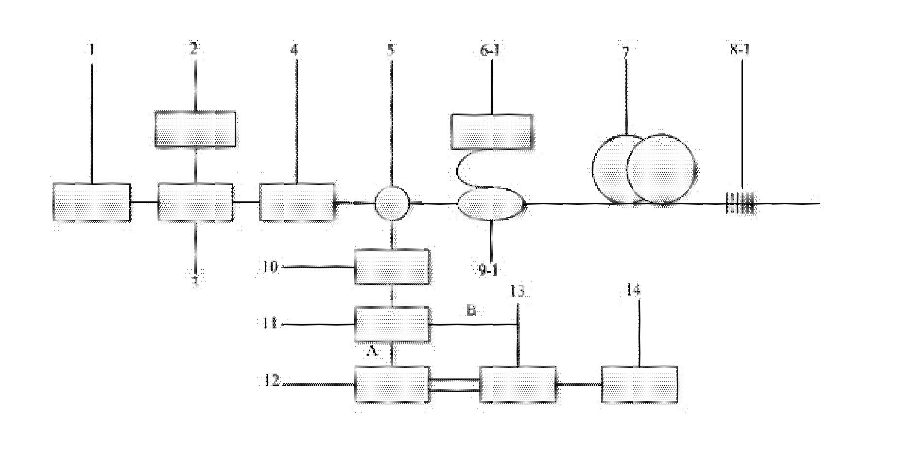
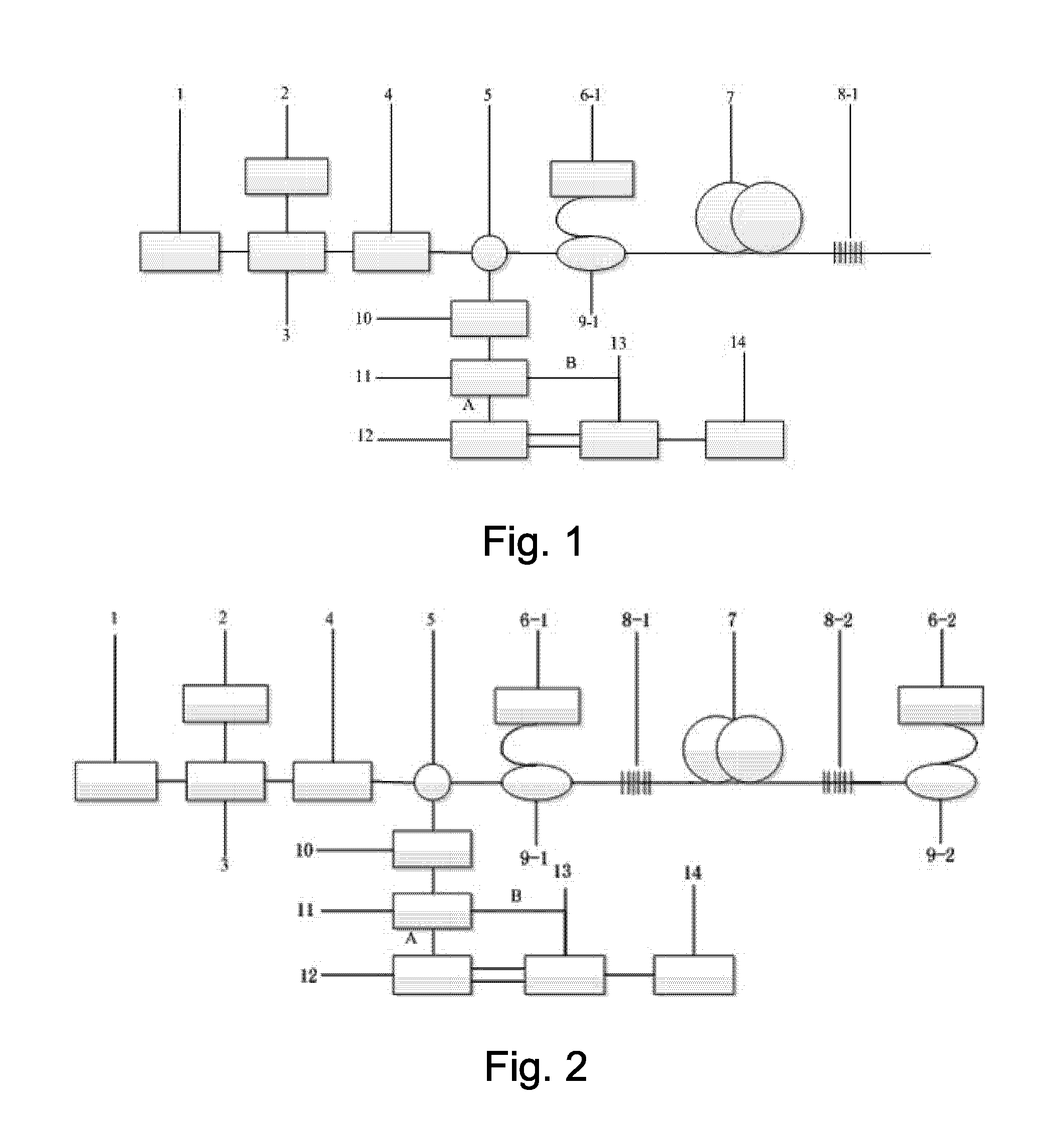
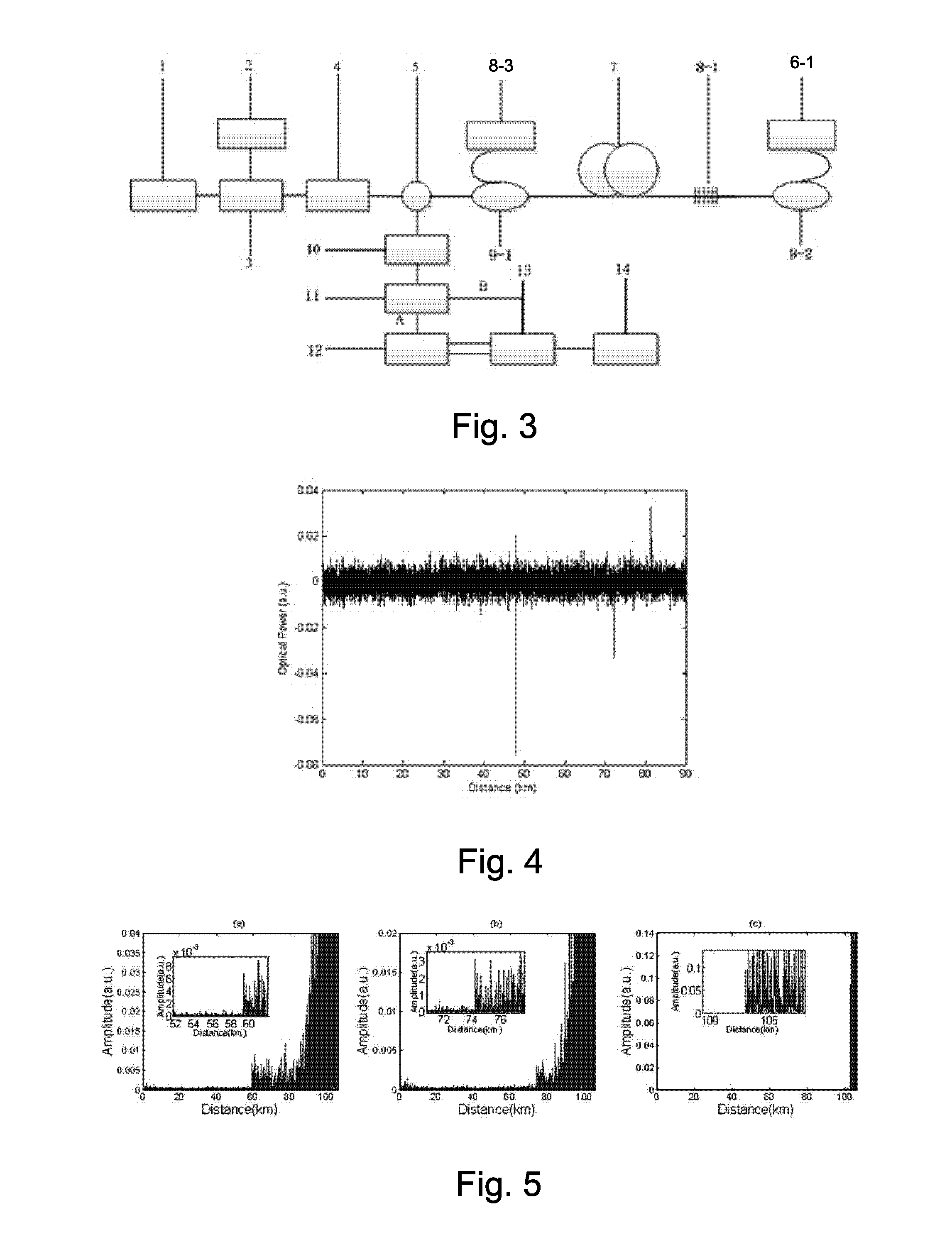
[0038]Referring to FIG. 2 of the drawings, according to a preferred embodiment of the present invention, a long-distance polarization and phase-sensitive optical time-domain reflectometry of a distributed Raman amplification based on optical fiber random lasers generated by bilateral pumps, comprises a laser (1), an arbitrary waveform generator (2), an acousto-optic modulator (3), an erbium-doped fiber amplifier (4), a circulator (5), a first 1365 nm pump laser source (6-1), a first fiber Bragg grating (8-1), sensing optical fibers (7), a second fiber Bragg grating (8-2), a second 1365 nm pump laser source (6-2), a band-pass filter (10), a first wavelength division multiplexer (9-1), a second wavelength division multiplexer (9-2), a 3 dB coupler (11), a polarization beam splitter (12), a photoelectric detector array (13) and a multi-channel A / D data collector (14).

[0039]The laser (1) is an externally modulated laser. An output terminal of the laser (1) and an input terminal of the a...


PUM


Abstract

A long-distance polarization and phase-sensitive reflectometry based on random laser amplification for extending a sensing distance includes a long-distance polarization and phase-sensitive reflectometry of a distributed Raman amplification based on optical fiber random lasers generated by unilateral pumps, a long-distance polarization and phase-sensitive reflectometry of a distributed Raman amplification based on optical fiber random lasers generated by bilateral pumps, and a long-distance polarization and phase-sensitive reflectometry of a Raman amplification based on a combination of optical fiber random lasers generated by unilateral pumps and a common Raman pump source, which are applied in optical fiber perturbation sensing and have a capability of greatly improving a working distance of a sensing system and a high practicability.

Description

BACKGROUND OF THE PRESENT INVENTION[0001]1. Field of Invention[0002]The present invention relates to a field of optical fiber sensing technology, and more particularly to a long distance polarization and phase-sensitive optical time-domain reflectometry having optical fiber random lasers as a distributed pump source.[0003]2. Description of Related Arts[0004]In the distributed optical fiber transmission technology, the optical fibers are both the transmission medium and the sensing elements; meanwhile, the optical fibers obtain the spatial distribution states of the measured parameters at a whole length of the optical fibers and the information changes of the measured parameters over time, so it is very suitable for the optical fibers to be applied in the safety and protection of long-distance optical cables and the peripheral security based on the optical cables. Because the phase and the polarization state of the light pulses transmitted in the optical fibers are very sensitive to ...

Claims


Application Information

Patent Timeline
Patent Type & Authority Patents(United States)
IPC IPC(8): G01J5/00G01D5/353G01J1/42G01J5/10
CPCG01D5/35354G01J1/42G01J5/10
Inventor RAO, YUNJIANGWANG, ZINANRAN, ZENGLING
Owner UNIV OF ELECTRONICS SCI & TECH OF CHINA
Learn More