Electric power converting apparatus and induction heating apparatus
a technology of induction heating and converting apparatus, which is applied in the direction of induction heating, power conversion systems, induction current sources, etc., can solve the problems of reducing the efficiency of the electric power converting apparatus, reducing the efficiency of the pulsing charging/discharging current reduction, and not considering the reduction of pulsing charging/discharging current, so as to reduce the ripple current flowing through the capacitor more reliably, improve the accuracy of synchronization, and reduce the ripple curren
- Summary
- Abstract
- Description
- Claims
- Application Information
AI Technical Summary
Benefits of technology
Problems solved by technology
Method used
Image
Examples
embodiment 1
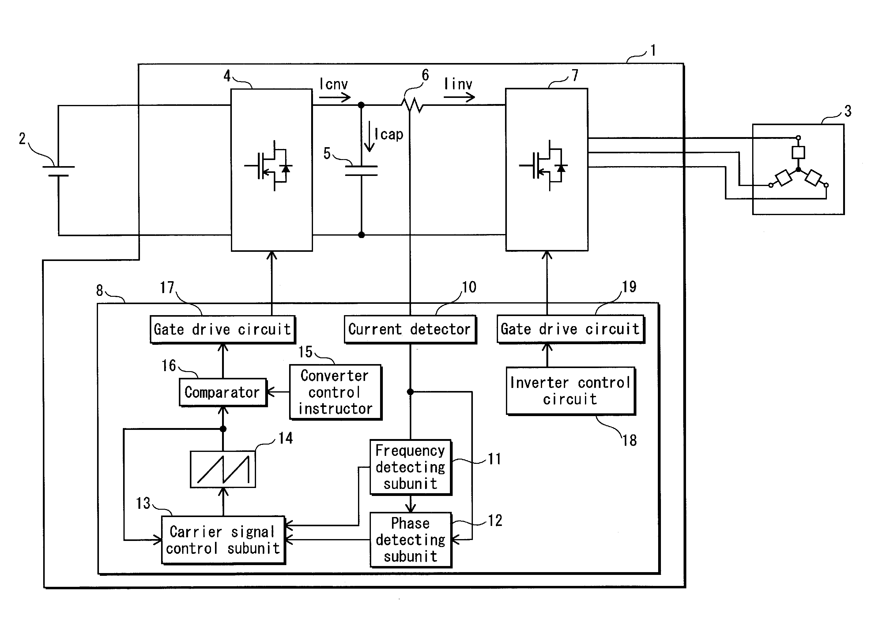
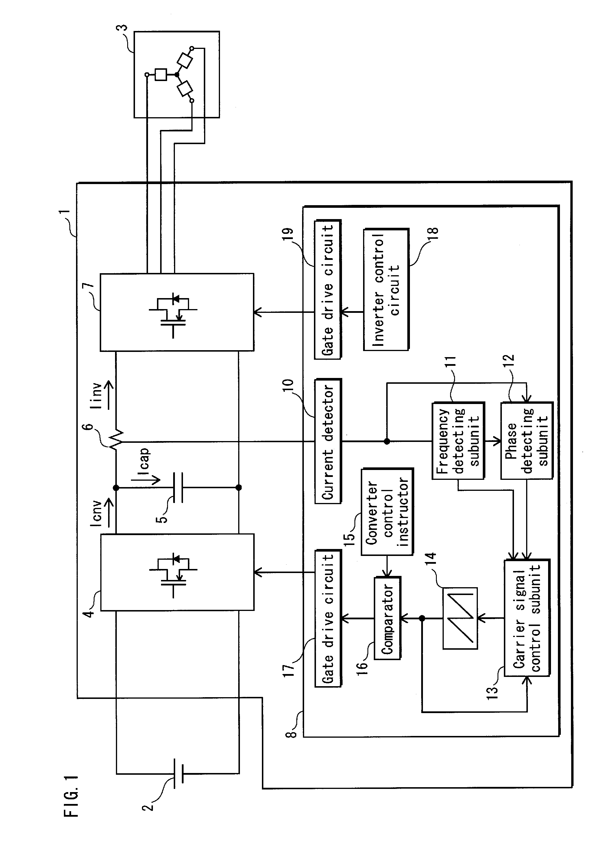
[0028]FIG. 1 shows a structure of a motor driving apparatus 1 that is an embodiment of an electric power converting apparatus of the present invention.
[0029]As FIG. 1 shows, the motor driving apparatus 1 includes a converter circuit 4, a capacitor 5, a current sensor 6, an inverter circuit 7 and a control unit 8. The converter circuit 4 is connected to a direct-current power source 2, and the inverter circuit 7 is connected to a motor 3.
[0030]The converter circuit 4 includes components such as an inductor and a switch. The converter circuit 4 boosts direct-current voltage supplied by the direct-current power source 2 to desired direct-current voltage, by switching on / off the switch according to Pulse Width Modulation (hereinafter, referred to simply as “PWM”) control of the control unit 8. The switch is a transistor such as an IGBT and a MOSFET.
[0031]The inverter circuit 7 is a three-phase inverter for driving the motor 3. The inverter circuit 7 includes a switch such as an IGBT and...
embodiment 2
[0060]FIG. 3 shows a structure of an induction heating apparatus 100 that is an embodiment of the induction heating apparatus of the present invention.
[0061]As FIG. 3 shows, the induction heating apparatus 100 includes a converter circuit, a capacitor 36, a current sensor 37, an inverter circuit 38, a heater 50 as a load circuit and a control unit 60. The converter circuit includes a diode bridge 32, a coil 33, a switch 34 and a diode 35. The heater 50 includes a current sensor 39, a heating coil 40, and a resonance capacitor 41.
[0062]Specifically, the induction heating apparatus 100 is a heating cooking instrument that includes a top plate, which is not illustrated, on an upper part of the heater 50, and heats a load pan placed on the top plate by supplying high frequency current from the inverter circuit 38 to the heating coil 40.
[0063]The converter circuit is connected to an alternating current source 31, and converts alternating-current voltage supplied by the alternating curren...
embodiment 3
[0077]The embodiment 2 as described above includes the current sensor 37 between the capacitor 36 and the inverter circuit 38, and directly detects the current Iinv flowing from the capacitor 36 to the inverter circuit 38. The embodiment 3 explains an example that does not need the current sensor disposed between the capacitor 36 and the inverter circuit 38, by using a result detected by the current sensor 39 that is included in a load.
[0078]FIG. 4 shows a structure of an induction heating apparatus 100a pertaining to an embodiment of the present invention.
[0079]As FIG. 4 shows, the induction heating apparatus 100a includes a converter circuit, the capacitor 36, the inverter circuit 38, the heater 50 and a control unit 60a. The converter circuit includes the diode bridge 32, the coil 33, the switch 34 and the diode 35. The heater 50 includes the current sensor 39, the heating coil 40 and the resonant capacitor 41.
[0080]The control unit 60a is a computer system including a microproce...
PUM
 Abstract
Description
Claims
Application Information
 - R&D
- Intellectual Property
- Life Sciences
- Materials
- Tech Scout
- Unparalleled Data Quality
- Higher Quality Content
- 60% Fewer Hallucinations
Browse by: Latest US Patents, China's latest patents, Technical Efficacy Thesaurus, Application Domain, Technology Topic, Popular Technical Reports.
© 2025 PatSnap. All rights reserved.Legal|Privacy policy|Modern Slavery Act Transparency Statement|Sitemap|About US| Contact US: help@patsnap.com


