Supercharge Your Innovation With Domain-Expert AI Agents!

Visual sight flexible gas flow indicator

a flexible gas flow and visual sight technology, applied in the direction of volume/mass flow by dynamic fluid flow effect, speed/acceleration/shock measurement, instruments, etc., can solve the problems of causing workers to be harmed, explosive conditions may persist for a very long time, and the use of air as purging gas is significantly increased the risk of an explosion. , to achieve the effect of simple construction, easy and fast installation, and low cos

Active Publication Date: 2015-11-17
PAYNE MARISELA
View PDF9 Cites 1 Cited by
  • Summary
  • Abstract
  • Description
  • Claims
  • Application Information

AI Technical Summary

Benefits of technology

The present invention provides a visual sight flexible gas flow indicator that allows workers or other personnel to easily see and locate where gas is flowing or leaking from a distance, reducing the risk of inhalation exposure or asphyxia. The indicator is easy to install, can be numbered for accurate documentation, and is simple in construction, inexpensive to manufacture, and reliable in operation. Additionally, the indicator helps workers avoid dangerous positions and reduces the need for climbing ladders or stairs.

Problems solved by technology

Using air as a purging gas significantly increases the risk of an explosion.
If there is enough liquid residue, the explosive conditions may persist for a very long time—longer than workers may be willing to wait before beginning their work.
However, the inerting and / or purging operations themselves may create hazards to workers by displacing the oxygen in the environment.
At a concentration in air below the LEL, there is not enough fuel to continue an explosion.
Concentrations lower than the LEL are “too lean” to explode but may still burn violently. as a sweep through to remove oxygen from vessels, piping and equipment prior to its commissio
Although workers may be equipped with LEL meters, many LEL meters will not read properly when oxygen levels are less than 10 percent.
Without enough oxygen, these meters can give an incorrect low reading even if flammable vapors and gases still remain.
Nitrogen can be very deadly.
Each year many accidents and deaths involving nitrogen occur.
If a continuous flow of nitrogen is released into air, the oxygen level in the air depletes very fast and can choke a person who is breathing this nitrogen-rich air.
Thus, a worker who is carrying out a vessel purging and / or inerting operation or a follow-up inspection in a typical petrochemical plant (where the vessel most likely was purged with nitrogen to rid it of explosive vapors), or somebody who is even standing near or in the vicinity of a vessel that has nitrogen purging on, is at risk.
One of the problems with these types of sight indicators is that it requires a person to be relatively close to the device in order to observe flow within the pipe on which it is mounted.

Method used


Image

  • Visual sight flexible gas flow indicator
  • Visual sight flexible gas flow indicator

Examples


Embodiment Construction

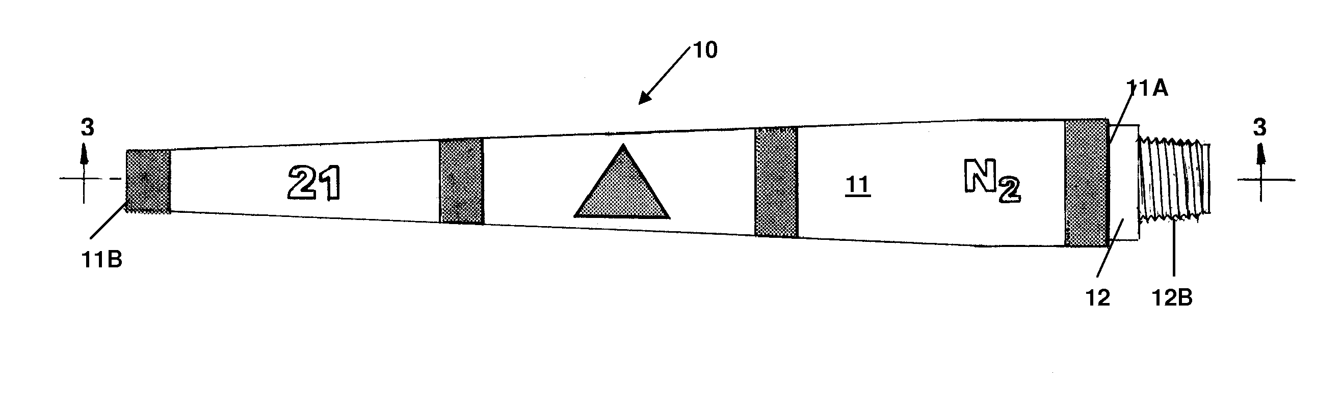
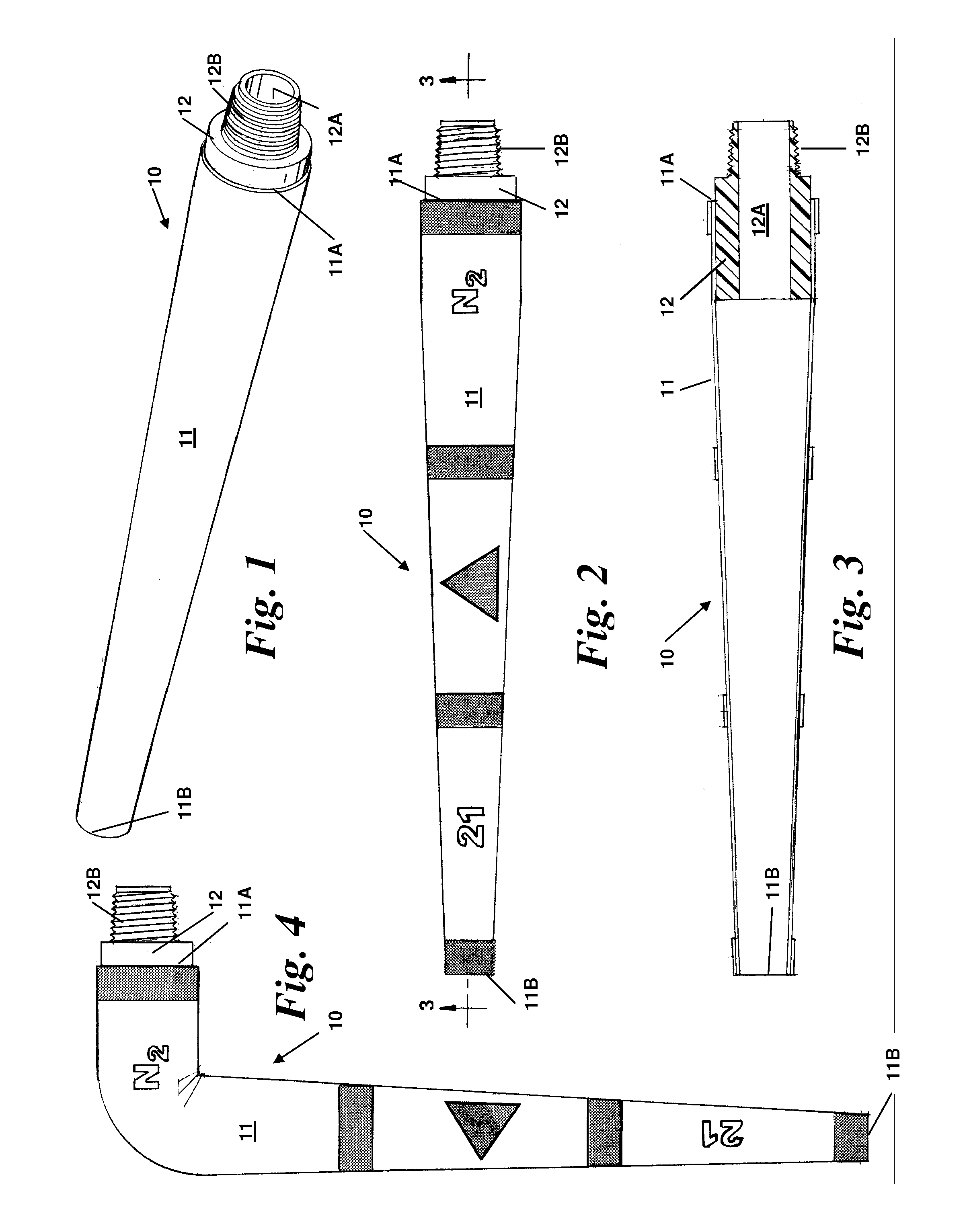
[0031]Referring to the drawings by numerals of reference, there is shown in FIGS. 1, 2, 3, and 4, a preferred visual sight flexible gas flow indicator 10. The visual sight flexible gas flow indicator 10 has a truncated conical sleeve 11 formed of a soft flexible water repellent fabric or synthetic material, or a blend of the two. If the fabric is not naturally immune to water absorption, it may be coated or treated to be water repellent.

[0032]The visual sight flow indicator flexible sleeve 11 tapers along its length from a larger diameter throat end 11A to a smaller diameter trailing end, or exit end 11B. The throat end 11A is secured to a threaded fitting 12 having an interior passageway 12A in fluid communication with the interior of the sleeve 11 of the visual sight flexible gas flow indicator 10. The throat end 11A is firmly secured to the threaded fitting 12 by any suitable retainer means 13, such as glue or epoxy, a clamp, or elastic band.

[0033]The threaded fitting 12 is confi...


PUM


Abstract

A visual sight flexible gas flow indicator has a truncated conical sleeve formed of flexible water repellent material tapered along its length from a larger diameter throat end to a smaller diameter exit end defining an interior. A threaded fitting secured to the throat end has an interior in fluid communication with the sleeve interior and is configured to be threadedly engaged in fluid flow communication with a conduit or bleeder valve of a vessel or piping system through which a gas to be monitored flows. The sleeve hangs flaccidly in a generally vertical position when no gas is flowing through the fitting and sleeve from the conduit or valve. Upon gas flowing through the fitting and sleeve from the conduit or valve, the sleeve becomes fully extended in a generally horizontal position to provide an external visual indication, from a distance, of gas flow and location of the leaking gas.

Description

BACKGROUND OF THE INVENTION[0001]1. Field of the Invention[0002]This invention relates generally to sight flow indicators for indicating fluid flow through or from a conduit and, more particularly, to a visual sight flexible gas flow indicator having a flexible truncated conical sleeve that connects to a gas conduit or bleeder valve and normally hangs flaccidly in a generally vertical position and becomes fully extended in a generally horizontal position to provide an external visual indication of gas flow or leakage easily seen a distance from the location of the flowing or leaking gas, and reduce the risks of inhalation exposure or asphyxia.[0003]2. Background Art[0004]Typically in industrial plants, such as refineries and petrochemical plants, a vessel, tank or piping system which previously contained hydrocarbons, must be periodically shut down, cleaned, and made safe by “purging” or “inerting” before resuming operations.[0005]“Purging” displaces or flushes out hydrocarbons by i...

Claims


Application Information

Patent Timeline
Patent Type & Authority Patents(United States)
IPC IPC(8): G01F1/05
CPCG01F1/05G01P13/00G01P13/0013G01F1/20G01F1/206
Inventor PAYNE, MARISELA
Owner PAYNE MARISELA
Features
  • R&D
  • Intellectual Property
  • Life Sciences
  • Materials
  • Tech Scout
  • Unparalleled Data Quality
  • Higher Quality Content
  • 60% Fewer Hallucinations
Learn More