
Method and system using an HVAC air handler and thermostat for building energy loss testing, monitoring and cost control

a technology of hvac air handler and thermostat, which is applied in the direction of lighting and heating apparatus, heating types, instruments, etc., can solve the problems of no known good location to measure average pressure, no known good location for observing average pressure, and significant leakage caused by return path resistance, etc., to achieve easy visualization, increase the effect of airflow through the envelope and reduce the cost of leakag

Inactive Publication Date: 2015-11-17
RICHARD R & SUZANNE N MEYER AB LIVING TRUST DTD 2 11 2003
View PDF14 Cites 36 Cited by
  • Summary
  • Abstract
  • Description
  • Claims
  • Application Information

AI Technical Summary

Benefits of technology

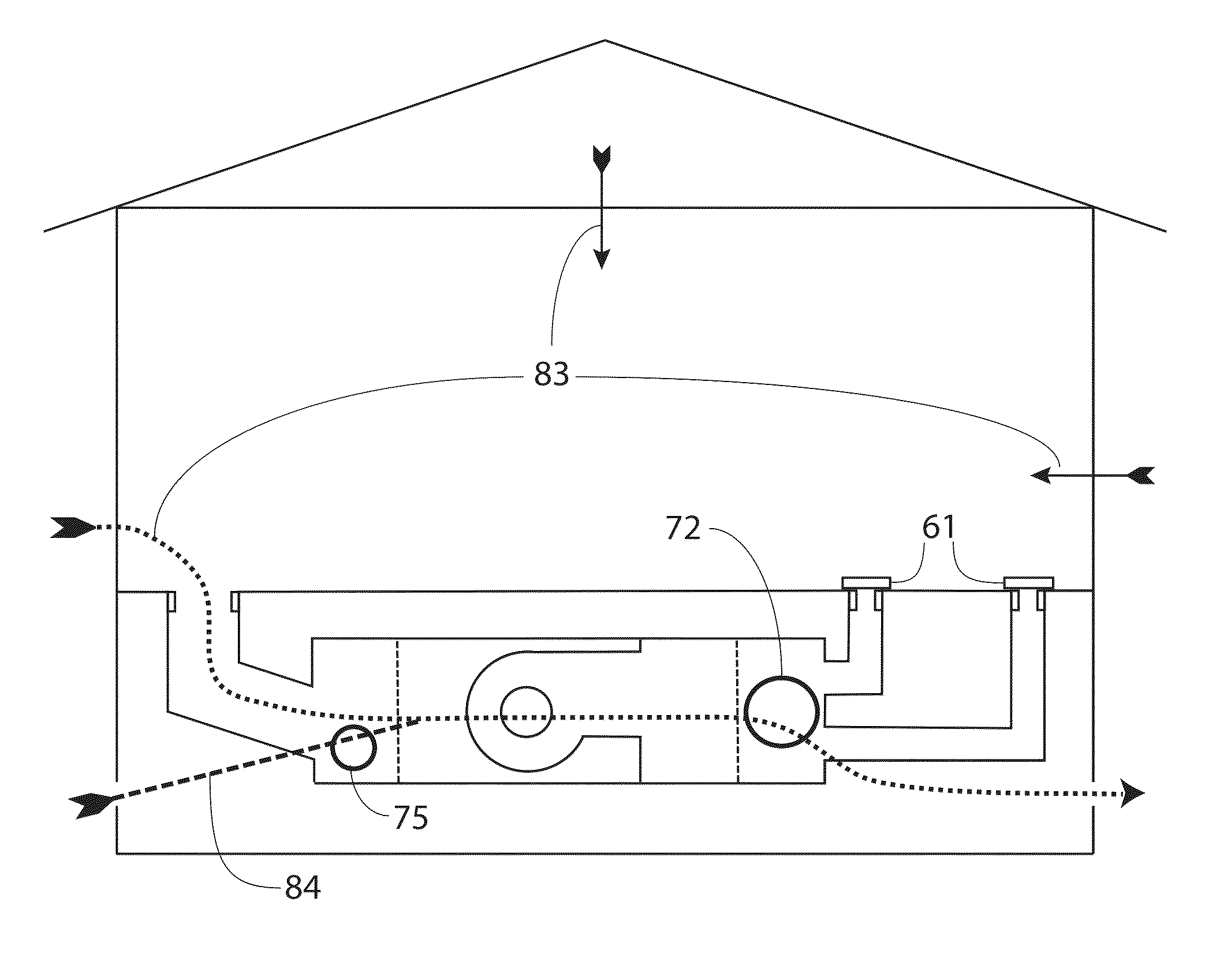
The patent describes a method for testing the air handler system to measure leakage and determine the amount of wasted energy caused by duct leaks. The system can measure supply duct leakage, return duct leakage, total duct leakage, predominant leakage, envelope infiltration, and envelope exfiltration. The method involves blocking the ducts and measuring the air flow through the blower. The system can also measure the external static pressure and adjust the blower speed to maintain the desired pressure. The testing can be done with the air handler in different configurations and can help identify and fix leaks. The method allows for accurate measurement of duct leakage and the amount of energy wasted.

Problems solved by technology

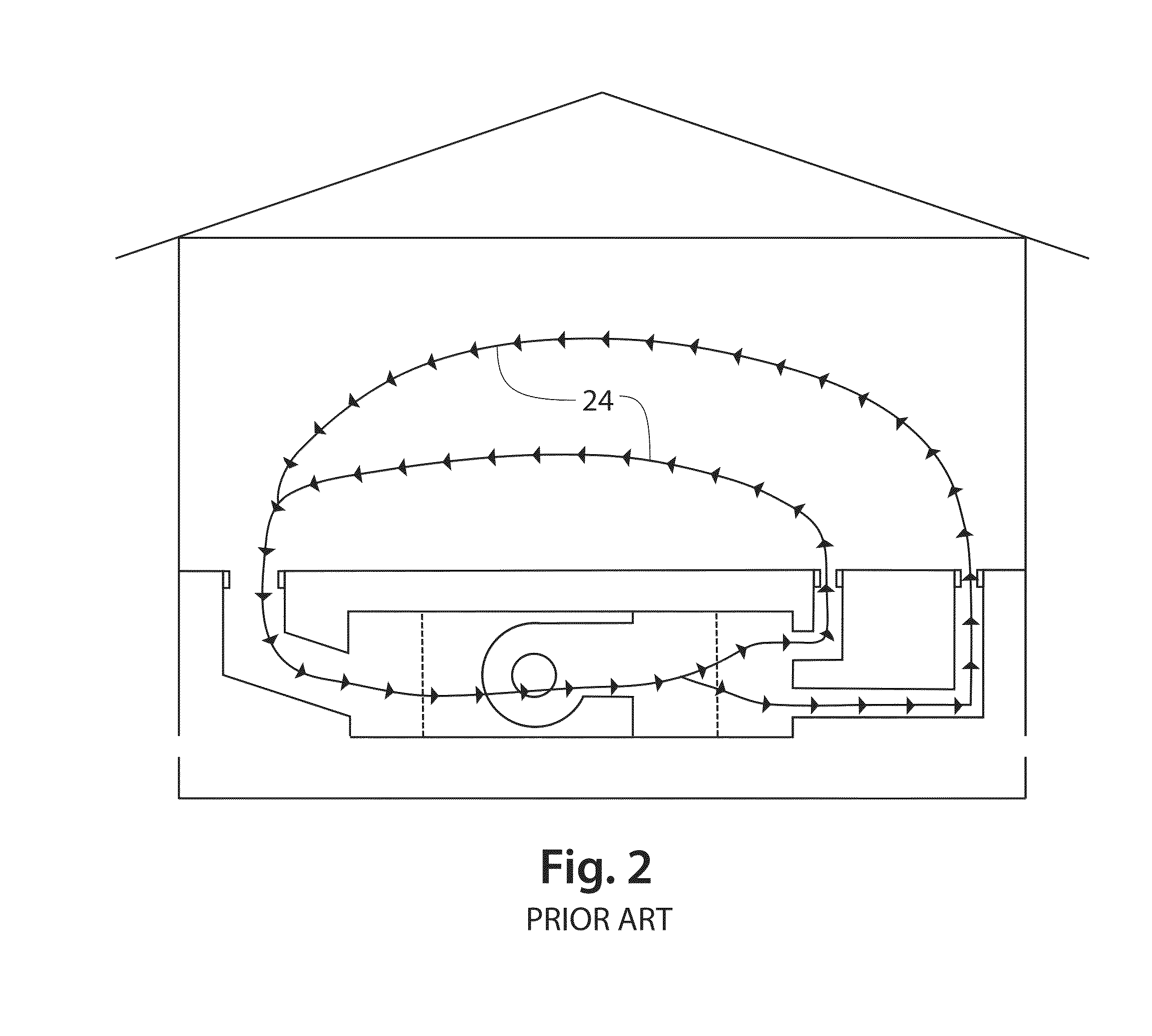
This method is subject to significant errors:1. Although the test uses a near-uniform pressure throughout the duct system, pressures during normal operation are far from uniform.
Converting leakage measured at a near uniform pressure to a percentage of system air flow under normal non-uniform conditions necessarily involves assumptions about the locations of leaks, which may be wrong.
The study also found actual average error rates of +−40%.2. Variation in pressure throughout the duct system during the test provides no known good location to measure average pressure.
Even this tedious process is error prone since results will vary depending on the relative locations of large leaks and the test locations.3. Normal airflow is commonly estimated at 400 CFM per ton of air conditioning or the furnace output in kBTU / h further divided by 21.6, whichever is larger.
Although the pressure drop through this flex duct varies depending on whether it is compressed or stretched, and whether it is straight or has turns, there is no compensation for this effect, introducing a further error.
Although the conventional test method has low accuracy, highly accurate and expensive test equipment is typically used, providing precision of measurement but low accuracy of the final test result.
Much energy may be wasted and carbon released into the environment over the full lifetime of a building by failing to seal the ducts of a building whose actual leakage is much higher than what was reported.
Unnecessary leak sealing expense is incurred as a result of a test in a building that falsely reported higher leakage than is actually present.
They also respond to energy price changes, thermostat setting changes, and occupancy patterns, in addition to problems requiring maintenance or repairs.
Separate energy monitors are available, but the cost of installing a sensor that detects the rate of use of natural gas, propane or heating oil is prohibitive, and such systems also cannot separate the effects of thermostat setting changes, and occupancy patterns from problems requiring maintenance or repairs.
They also cannot determine if an HVAC system is operating within manufacturer's specifications or building code requirements.

Method used


Image

  • Method and system using an HVAC air handler and thermostat for building energy loss testing, monitoring and cost control
  • Method and system using an HVAC air handler and thermostat for building energy loss testing, monitoring and cost control
  • Method and system using an HVAC air handler and thermostat for building energy loss testing, monitoring and cost control

Examples


embodiment

Sophisticated Embodiment

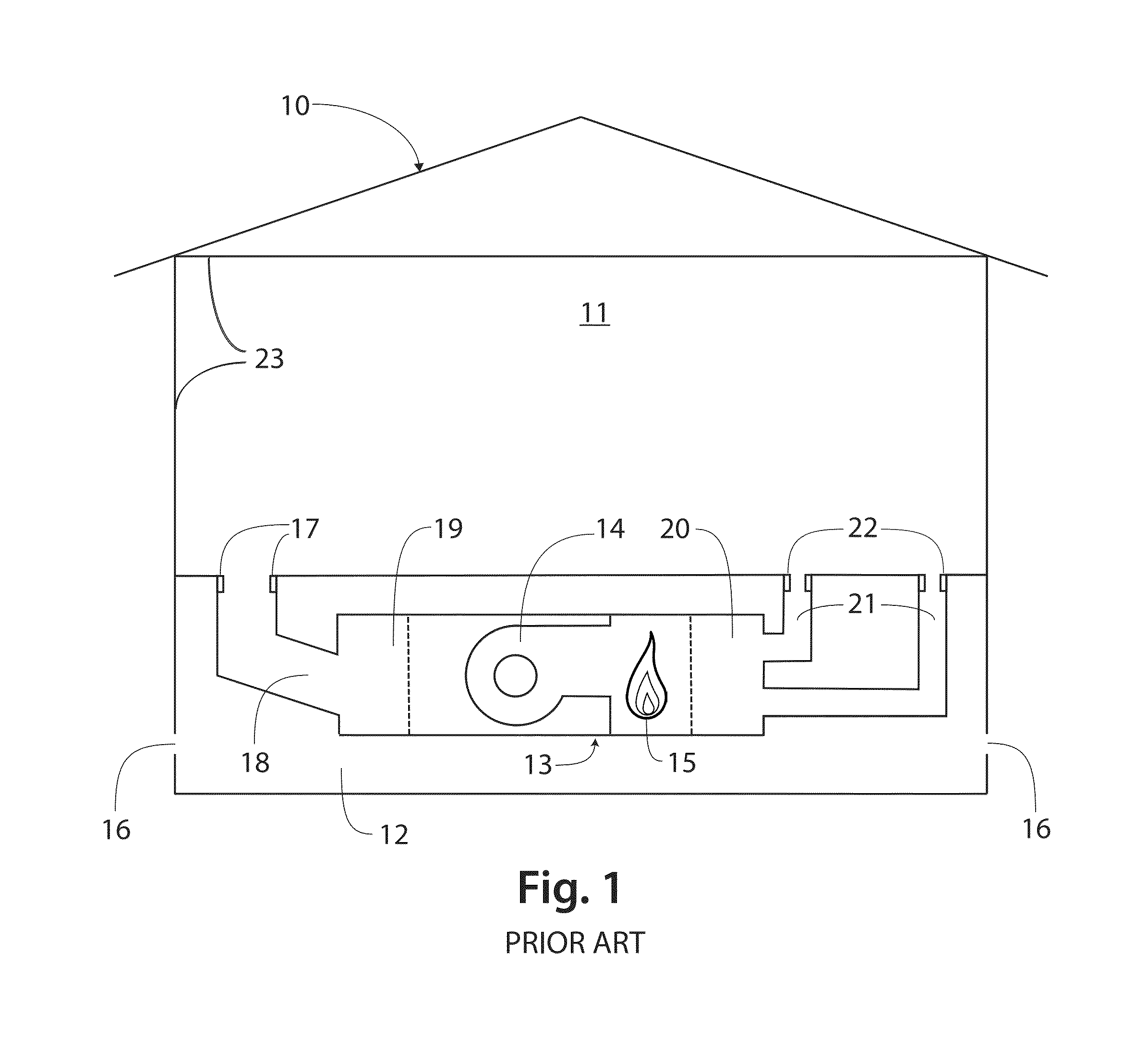
[0163]In another class of embodiments, one of which is depicted in FIG. 14, configuration, test and monitoring functions are integrated into a programmable thermostat assembly 140, using the microcontroller 141, thermistor 160, display 142 and keypad 143 in the thermostat, and the air handler control electronics 144, located inside the air handler assembly 13. The air handler assembly 13 contains blower 14 driven by motor 148, and burn valve 153. Motor 148 or control logic 149 may include a circuit breaker to prevent excessive power consumption by motor 148. In prior art thermostats that are easier to use, the functions of keypad 143 are performed by a touchscreen integrated into display 142. Recent programmable thermostats using prior art may also include wireless communications module 158 that connects the thermostat to a network. In operation according to the prior art, the thermostat 140 controls the blower relay 152, burner relay 154 and air conditioner ...


PUM


Abstract

An improved HVAC air handler and control system adapted for measuring and monitoring operating characteristics, the leakage of supply and return ducts to which it is connected, the infiltration leakage of the building it serves, the blockage of air return paths and the watts drawn and air flow generated by its blower. Leakages are measured by blocking outlets of all supply ducts or all return ducts, opening one side of the air handler to outdoor air, running the air handler blower, and measuring the air flow. Airflow may be measured by opening or closing orifices mounted in plenums attached to the air hander or built into the air handler cabinet, or by varying the speed of the blower motor, in connection with an integrated manometer. Thermostat firmware controls all functions.

Description

CROSS-REFERENCE TO RELATED APPLICATIONS[0001]This application claims the benefit of Method and System Using an HVAC Air Handler for Building Energy Loss Testing and Monitoring, Application 61 / 797,428, filed Dec. 6, 2012 by the same inventor, and Method and System Using an HVAC Air Handler for Building Energy Loss Testing and Monitoring, Application 61 / 958,942, Filed Aug. 8, 2013 by the same inventorFEDERALLY SPONSORED RESEARCH[0002]None.SEQUENCE LISTING[0003]None.BACKGROUND[0004]This application relates to advanced control systems for HVAC systems that integrate testing of forced air duct leakage and building envelope infiltration, the monitoring of energy efficiency in the conditioning of buildings, the prediction of financial costs or savings from thermostat setting changes, and the monitoring of ongoing operating parameters and space conditioning costs.[0005]Envelope infiltration and duct leakage are recognized as two of the largest wastes of energy in U.S. homes and other buildi...

Claims


Application Information

Patent Timeline
IPC IPC(8): G06F19/00G01M3/26F24F11/00G01M99/00
CPCG01M99/005F24F11/0009G01M3/26G01M3/2815F24F11/30F24F11/52F24F11/46
Inventor MEYER, RICHARD RECTOR
Owner RICHARD R & SUZANNE N MEYER AB LIVING TRUST DTD 2 11 2003
Learn More