
Device with a measurement arrangement for optical measurement of gases and gas mixtures, with compensation of environmental effects

a technology of optical measurement and environmental effects, applied in the direction of material analysis through optical means, instruments, transmissivity measurements, etc., can solve the problems of insensitivity to locally limited local contamination, inability to effectively measure gas concentration, and limited space available for installation

Active Publication Date: 2015-11-17
DRAGER SAFETY
View PDF11 Cites 0 Cited by
  • Summary
  • Abstract
  • Description
  • Claims
  • Application Information

AI Technical Summary

Benefits of technology

[0056]A protective element, which is designed to prevent the passage of contaminants from the measurement environment into the measuring cuvette, is preferably arranged at the gas inlet towards the measurement environment.
[0086]An effect that is summarily on the order of magnitude that corresponds essentially to the effect of the atmospheric humidity at the measurement wavelength λM is obtained in the first and second variants of this first embodiment at the first reference detector from the weaker and stronger effects of the direct and indirect effect of the atmospheric humidity on the reference wavelengths λR1, λR2 relative to the effect at the measurement wavelength λM. A summary zero signal, which can be used for the measured signal as a reference variable for determining the gas concentration, is also available with this summary effect under the effect of moisture in the operating and analyzing unit. The gas concentration of the target gas is determined in the operating and analyzing unit by referring and relating the measured signal to the zero signal. The moisture effect on the gas concentration determined in the operating and analyzing unit is eliminated in this manner, because it affects both the measured signal corresponding to the measurement wavelength λM and the summary zero signal, which summarily corresponds to the first and second reference wavelengths, in the same direction.
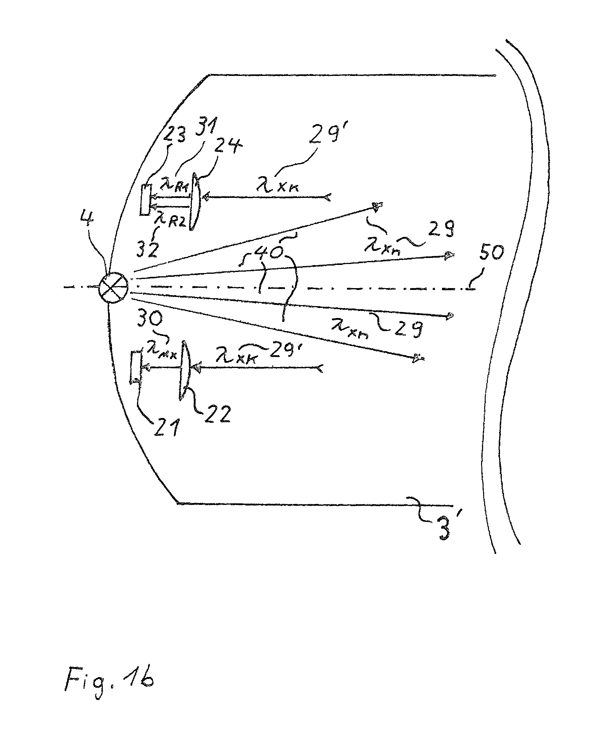
[0108]As was described above, the first and second reference wavelengths λR1, λR2 are selected, on the one hand, such that there will be no signal reductions due to the target gas or due to other gases of the measurement environment. Furthermore, the first and second reference wavelengths λR1, λR2 are selected to be such that environmental effects, especially the direct effect of atmospheric humidity as well as the indirect effect of the atmospheric humidity due to the salt content, lead, in combination in the zero signal determined in the operating and analyzing unit, to the same effect as a signal reduction, which corresponds to the effect manifested as signal reduction at the measurement wavelength λM.
[0110]In a second variant of this second embodiment, the first reference wavelength λR1 is selected to be such that the direct and indirect effects of the atmospheric humidity are more pronounced than at the measurement wavelength λM and the second reference wavelength λR2 is selected to be such that the direct and indirect effects of the atmospheric humidity are less marked than at the measurement wavelength λM. An effect, which corresponds to the effect of the atmospheric humidity at the measurement wavelength λM at the measuring detector, is obtained in both variants of this second embodiment from the weaker and stronger effect of the direct and indirect effects of the atmospheric humidity on the signal corresponding to the first reference wavelength λR1 at the first reference detector and on the signal corresponding to the second reference wavelength λR2 at the second reference detector in the operating and analyzing unit. Thus, a zero signal, which is suitable for the measured signal as a reference variable for determining the gas concentration, is available under the effect of moisture in the operating and analyzing unit in this second embodiment as well.
[0112]The moisture effect on the gas concentration determined in the operating and analyzing unit is eliminated in this manner, because it acts in the same direction on both the measured signal corresponding to the measurement wavelength λM and the zero signal, which was determined on the basis of the signal of the first and second reference wavelengths at the first and second reference detectors.
[0156]It can be seen from this that the moisture effect k2 can be eliminated in Formula [2] and the target gas concentration is thus obtained from the signal reduction k1 relative to the zero signal A(0, λM) at the measurement wavelength λM and the summary reference signal A(λR1, λR1) at the reference wavelengths λR1, λR2.

Problems solved by technology

This insensitivity to locally limited local contaminations arises from the fact that since the light is coupled from the light source into the multireflection cuvettes in the undirected form, statistically locally random and varying reflections occur on the reflecting surfaces, both as single, double and even multiple reflections, before the light reaches the detector.
As a result, a locally limited local contamination does not become an effective drawback for the gas concentration measurement due to the statistically random and continuously varying reflections.
The overall size of the cuvette is preset essentially by the space available for installing the gas-measuring device, but the space available for installation has its limitations for mobile gas-measuring devices concerning applicability for mobile applications.
The length of the measured section within the cuvette is limited, on the one hand, by the losses of light over the measured section itself and the light absorption by the target gas, and further essential limitations arise from the losses that occur due to the optical components and are due to the sensitivity of the detector used.
Such heating is not quite uncritical for using the measurement arrangement in areas with explosion hazard.
The consequence of this is always an undesired, high energy consumption for such a measurement arrangement.
Any increase in the heat output during the operation is associated, however, with the drawback for mobile devices, of both an explosion-proof design and a non-explosion-proof design, that the quantity of electric energy needed therefore must be carried along additionally in the form of an energy storage device (batteries rechargeable batteries), which would result in a disadvantageous excess weight for mobile applications, or that the available operating time becomes shorter for mobile application without increasing the weight of the device, which is not realistic in case of the application scenarios of mobile gas-measuring devices in practical use.
The explosion protection measures must be massively intensified for a measurement arrangement of an explosion-proof design, which is likewise associated again with drawbacks for the mobile use, besides a globally increased weight and volume, and additionally also has consequences for the construction and design of the protective element at the gas inlet.
This circumstance leads to a very massive construction for the protective element, which makes the access of gas difficult and causes disadvantageous changes in the measurement properties, and, in particular, the response characteristic in case of a gas exchange, usually characterized by the so-called t10-90 time, is adversely effected by the longer diffusion time of the gas through the protective element, which is now necessary, in such a way that the warning function of the measurement arrangement will not occur with a short delay after a change in concentration in the measurement environment.
Further difficulties arise in the embodiment for the use of the measurement arrangement in areas with explosion hazard, because the quantity of energy being carried along and the temperatures of elements in the measurement arrangements are limited by regulatory requirements.
Thus, it is not possible in a practical embodiment to prevent condensation nearly completely by means of increasing the heat output while bringing about a marked reduction of the relative humidity of the air in the measuring cuvette to values between 5% and 10% for both a measuring cuvette of non-explosion-proof design and a measuring cuvette of an explosion-proof design.
The consequence of this is that these wavelengths (2,215 nm, 2,300 nm, 2,385 nm) are unsuitable for a measurement arrangement designed as a point detector for the measurement of alkanes by means of a cuvette, whose effective optical path length is markedly shorter than 30 cm due to the overall size.
This permanent operating situation determines the measurement conditions for the measurement properties of the measurement arrangement over rather long periods of time ranging from months to years as a measurement condition with the continuous presence of atmospheric humidity in the measuring cuvette, and only the formation of condensation and droplets of water on the walls of the cuvette and the optical components, such as lenses, filters and mirrors can be prevented by heating, but the continuous presence of atmospheric humidity at variable and unknown concentrations cannot.
The effect of these environmental effects, especially of the continual, further supply of atmospheric humidity into the cuvette by the crystalline hygroscopic salt film, cannot be compensated by heating alone, especially for a measurement arrangement of an explosion-proof design in scenarios of use such as offshore drilling platforms or onboard ships.
The continual penetration of atmospheric humidity into the cuvette due to the hygroscopic effect of the fine crystalline salt films cannot be fully compensated even for a measurement arrangement of a non-explosion-proof design by changing the heating of the detector and / or cuvette, e.g., by increasing the heat output or by raising the heating temperature or even by a cyclically performed heating of the entire measurement arrangement.
These environmental effects likewise cannot be fully compensated either by the use of additional sensors, such as temperature, moisture and pressure sensors in the cuvette or at the detectors.

Method used


Image

  • Device with a measurement arrangement for optical measurement of gases and gas mixtures, with compensation of environmental effects
  • Device with a measurement arrangement for optical measurement of gases and gas mixtures, with compensation of environmental effects
  • Device with a measurement arrangement for optical measurement of gases and gas mixtures, with compensation of environmental effects

Examples


Embodiment Construction

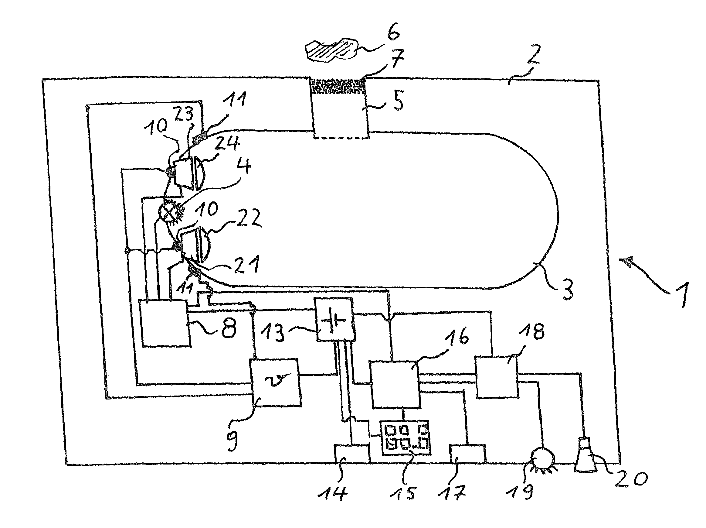
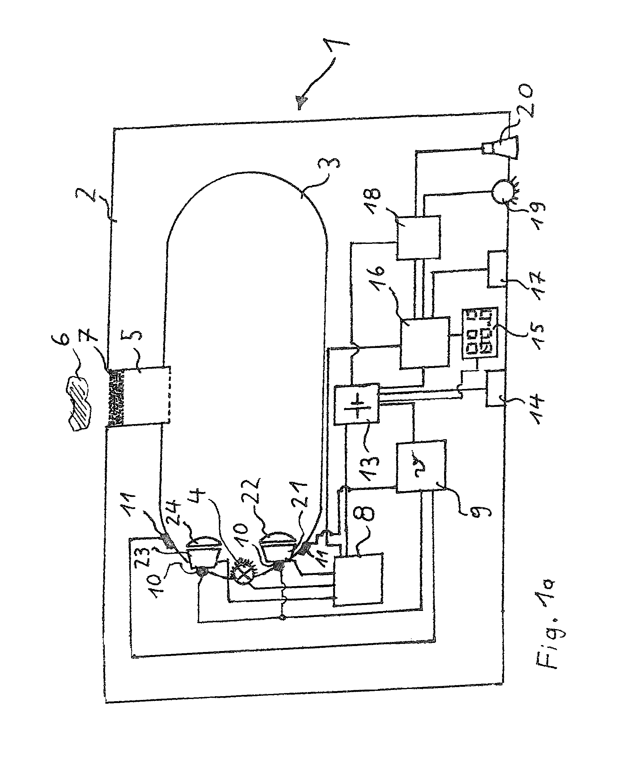
[0167]Referring to the drawings in particular, FIG. 1a shows a first measurement arrangement 1 for the infrared optical measurement of gases and gas mixtures, with compensation of environmental effects, with a housing 2 with a measuring cuvette 3, an operating and analyzing unit 8, a driving unit 9, an energy supply unit 13 with a feed interface 14 arranged thereon, a communication unit 16, to which a display unit 15, an alarm unit 18 and a data interface 17 are connected.

[0168]The operating and analyzing unit 8 is connected to the driving unit 9, the energy supply unit 13 and the communication unit 16. The energy supply unit 13 supplies the alarm unit 18, the display unit 15, the driving unit 9, the communication unit 16 and the driving unit 9 with electric energy.

[0169]An optical alarm generator 19 and an acoustic alarm generator 20 are connected to the alarm unit 18.

[0170]The measuring cuvette 3 comprises a radiation source 4, a gas inlet 5 with a protective element 7 arranged to...


PUM

PropertyMeasurementUnit
wavelengthaaaaaaaaaa

Abstract

A device for optical detection of a target gas in gas mixtures includes an operation and evaluation unit, a measurement cuvette with optically reflective surfaces on its interior walls and a gas inlet to the environment, a radiation source, a measuring detector and a reference detector unit provided on the measurement cuvette. The measuring detector and the reference detector unit detect the light of the radiation source and produce electrical signals corresponding to the intensity of the detected light. An optical bandpass filter element, constructed to transmit light of a measurement wavelength, is arranged upstream of the measuring detector. An optical double-bandpass filter unit, that transmits light of a first reference wavelength and light of a second reference wavelength, is arranged upstream of the reference detector unit. The operation and evaluation unit operates the radiation source and acquires the electrical signals of the measurement detector and the reference detector unit.

Description

CROSS REFERENCE TO RELATED APPLICATIONS[0001]This application is a United States National Phase Application of International Application PCT / EP2012 / 062843 filed Jul. 2, 2012 and claims the benefit of priority under 35 U.S.C. §119 of German Utility Model DE 20 2011 102 765.5 filed Jul. 2, 2011, the entire contents of which are incorporated herein by reference.FIELD OF THE INVENTION[0002]The present invention pertains to a measurement arrangement for the infrared optical measurement of gases and gas mixtures with compensation of environmental effects.BACKGROUND OF THE INVENTION[0003]The possibility for analyzing gas mixtures is an essential boundary condition in the monitoring of industrial plants for an incident-free and safe operation, especially against the background of the increasing degree of automation. To make it possible to recognize gases escaping in case of an incident as accurately and rapidly as possible, for example, in major industrial plants, in petrochemical plants or...

Claims


Application Information

Patent Timeline
Patent Type & Authority Patents(United States)
IPC IPC(8): G01N21/61G01N21/03G01N21/09G01N21/15G01N21/31G01N21/3504
CPCG01N21/61G01N21/031G01N21/0332G01N21/09G01N21/15G01N21/314G01N21/3504
Inventor STOCK, BURKHARDHAACK, NILSDIEKMANN, WILFRIEDLANGE, BJORN
Owner DRAGER SAFETY
Learn More