Compact antenna system

a compact, antenna technology, applied in the direction of antennas, antenna details, electrical equipment, etc., can solve the problems of reducing the accuracy with which the position of the navigation receiver can be determined, multi-path signals, and unwieldy pole-mounted assemblies, etc., to achieve the effect of convenient integration and low manufacturing cos

Active Publication Date: 2015-12-01
TOPCON POSITIONING SYST INC
View PDF13 Cites 2 Cited by
  • Summary
  • Abstract
  • Description
  • Claims
  • Application Information

AI Technical Summary

Benefits of technology

[0019]Embodiments of the antenna system can be configured for linearly-polarized radiation or circularly-polarized radiation. Embodiments of the antenna can be configured for single-frequency band or dual-frequency band operation. Embodiments of the antenna system can be inexpensively manufactured with flexible printed circuit boards. Embodiments of the antenna system are light weight and compact and can be readily integrated with a surveying pole for applications with global navigation satellite systems.

Problems solved by technology

The weight of the antenna should also be small enough to ensure easy handling of the pole-mounted assembly: if the weight is excessive, the center-of-gravity is raised too high, and the pole-mounted assembly is unwieldy.
Multipath signals reduce the accuracy with which the position of the navigation receiver can be determined.
The antenna system 100, however, suppresses the multipath signal only within a narrow bandwidth; and the stacked antenna construction has the further disadvantages of heavy weight and large dimensions.
Suitable dielectric materials over the operating frequency bands, however, have a high density; consequently, the weight of the antenna system increases significantly.
In both instances, the antenna extends considerably beyond the pole (particularly along lateral dimensions), and the configuration of outer mounting elements reduces the stability of the overall pole-mounted assembly.

Method used


Image

  • Compact antenna system
  • Compact antenna system
  • Compact antenna system

Examples


Embodiment Construction

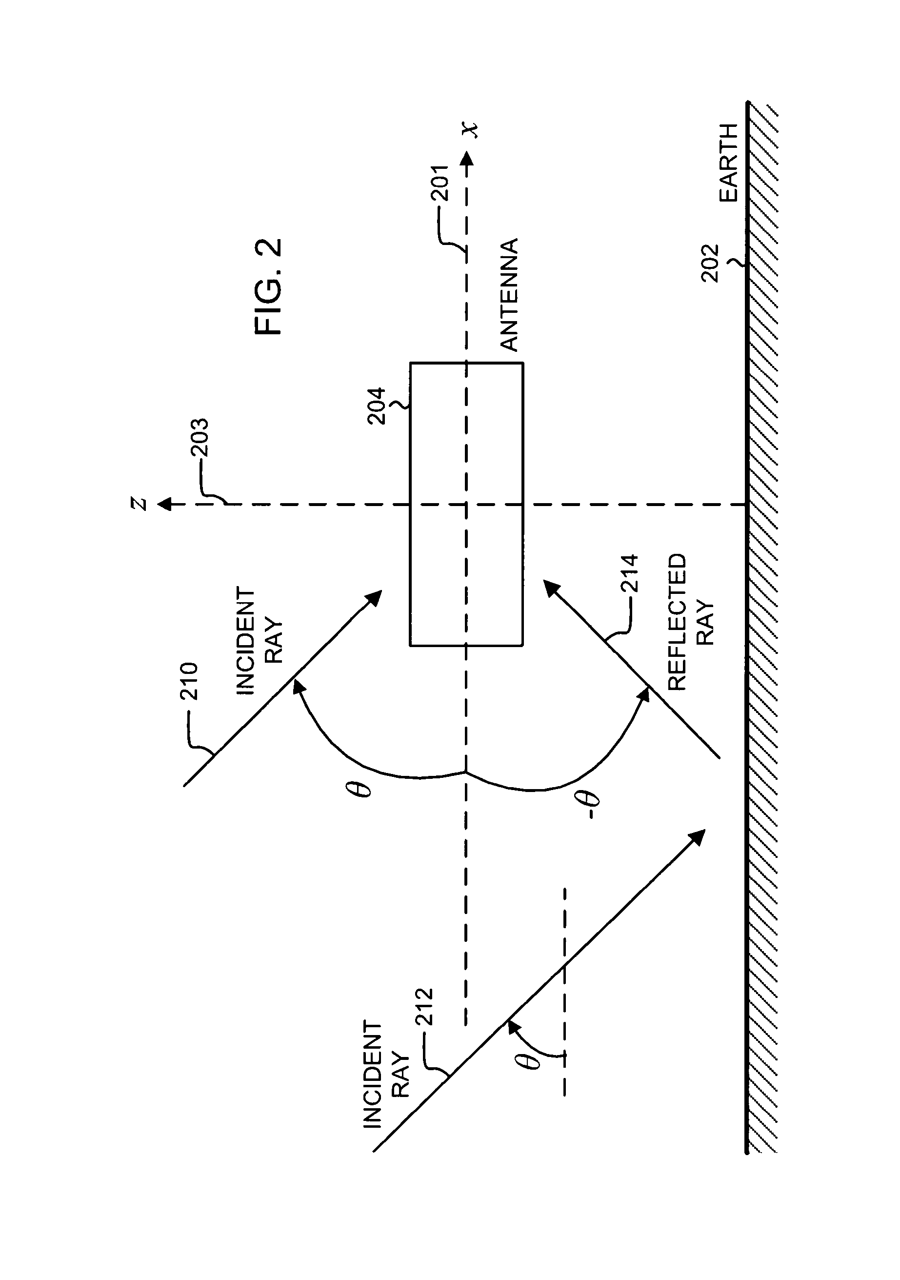
[0044]FIG. 2 shows a schematic of an antenna 204 positioned above the Earth 202. The antenna 204, for example, can be mounted on a surveying pole (not shown) for surveying applications. The plane of the figure is the x-z plane, defined by the x-axis 201 and the z-axis 203. The +y direction points into the plane of the figure. In an open-air environment, the +z (up) direction, also referred to as the zenith, points towards the sky, and the −z (down) direction points towards the Earth. The horizon falls on the x-y plane. Herein, the term Earth includes both land and water environments. To avoid confusion with “electrical” ground, as used in reference to a ground plane, “geographical” ground, as used in reference to land, is not used herein.

[0045]In FIG. 2, electromagnetic waves are represented as rays, incident upon the antenna 204 at an incident angle θ with respect to the x-axis. The horizon corresponds to θ=0 deg. Rays incident from the open sky, such as the ray 210 and the ray 212...


PUM


Abstract

An antenna system for global navigation satellite systems includes a ground plane, an active antenna disposed above the ground plane, and a passive antenna disposed below the ground plane. The active antenna includes a conducting ring substantially parallel to the ground plane. A radiating conductor passes through substantially the center of the conducting ring; the ends of the radiating conductor are electrically connected to the conducting ring. An excitation pin is electrically connected to the radiating conductor. A set of reactive impedance elements is electrically connected between the conducting ring and the ground plane. The set of reactive impedance elements is disposed substantially orthogonal to the ground plane. The passive antenna is similar to the active antenna, except the passive antenna does not have an excitation pin. The antenna system effectively suppresses multipath reception, and its compact size and light weight make it suitable for integration with a surveying pole.

Description

BACKGROUND OF THE INVENTION[0001]The present invention relates generally to antennas, and more particularly to a compact antenna system with a reduced directional pattern in the backward hemisphere.[0002]Global navigation satellite systems (GNSSs) can determine locations with high accuracy. Currently deployed GNSSs include the United States Global Positioning System (GPS) and the Russian GLONASS. Other GNSSs, such as the European GALILEO system, are under development. GNSSs are used in a wide range of applications, such as surveying, geology, and mapping.[0003]In a GNSS, a navigation receiver receives and processes radio signals transmitted by satellites located within a line-of-sight of the navigation receiver. A critical component of a GNSS is the receiver antenna. Key properties of the antenna are bandwidth, multipath rejection, size, and weight.[0004]High-accuracy navigation receivers typically process signals from two frequency bands. Two common frequency bands are a low-freque...

Claims


Application Information

Patent Timeline
Patent Type & Authority Patents(United States)
IPC IPC(8): H01Q1/00H01Q5/00H01Q23/00H01Q5/328H01Q1/12H01Q9/04H01Q19/00H01Q5/40
CPCH01Q5/328H01Q1/1242H01Q23/00H01Q9/0464H01Q19/00H01Q5/40
Inventor TATARNIKOV, DMITRY VITALIEVICHASTAKHOV, ANDREY VITALIEVICHSHAMATULSKIY, PAVEL PETROVICH
Owner TOPCON POSITIONING SYST INC
Why Eureka
Try Eureka