Liquid-cooled internal combustion engine with afterrun cooling, and method for operating an internal combustion engine of said type

a liquid-cooled internal combustion engine and after-run cooling technology, which is applied in the direction of engine cooling apparatus, failure safe, cylinders, etc., can solve the problems of first weakened strength of mechanical and thermally high-loaded cylinder heads or blocks, heat not first conducted to the surface, and proved problems, so as to prevent irreversible damage

Active Publication Date: 2015-12-29
FORD GLOBAL TECH LLC
View PDF23 Cites 2 Cited by
  • Summary
  • Abstract
  • Description
  • Claims
  • Application Information

AI Technical Summary

Benefits of technology

[0023]According to the disclosure, the flow cross section of the connecting line leading through the at least one liquid-cooled component is variable and is reduced when the internal combustion engine is in operation, because, owing to the high coolant pressure when the coolant pump is active, the valve which adjusts in a pressure-dependent manner is situated in the first working position and opens up only a relatively small cross section of the connecting line. Adequate cooling of the component is nevertheless ensured by the relatively small cross section in interaction with the high coolant pressure.
[0024]As a result of the transition from the second working position into the first working position, the valve reduces the coolant delivery via the connecting line when the internal combustion engine is in operation. The reduced coolant delivery has advantages in particular with regard to the problem of the re-enrichment of the coolant with air in the ventilation vessel.
[0025]When the internal combustion engine is switched off, the valve, owing to a reduced coolant pressure, switches from the first working position into the second working position, in which a relatively large cross section of the connecting line is opened up. As a result of enlargement of the flow cross section, the flow resistance in the connecting line is reduced. In this way, in turn, when the internal combustion engine is switched off, the delivery of coolant by means of the thermosiphon effect is assisted and adequate afterrun cooling when the internal combustion engine is out of operation, that is to say switched off, is ensured.
[0026]According to the disclosure, as a valve, use is made of a self-controlling valve which, as a function of the coolant pressure, varies the flow cross section of the connecting line and thereby controls the coolant throughput through the at least one liquid-cooled component, specifically in such a way that the cross section decreases with rising coolant pressure. Consequently, in the internal combustion engine according to the disclosure, it is the case not only that the coolant delivery when the internal combustion engine is in operation is reduced, but rather also that the coolant delivery and thus the cooling when the internal combustion engine is not in operation is forced, that is to say increased, by opening the valve, whereby improved afterrun cooling is realized. This results in a supply of coolant to the at least one liquid-cooled component according to demand, wherein the delivery of the coolant is based on the thermosiphon effect.

Problems solved by technology

Here, the mechanically and thermally highly loaded cylinder head or block is firstly weakened in terms of its strength as a result of the provision of the coolant ducts.
Secondly, the heat need not firstly be conducted to the surface to be able to be dissipated, as is the case with the air-type cooling arrangement.
Liquid-cooled components of the internal combustion engine which are connected into the cooling circuit of the internal combustion engine by means of a connecting line and which require afterrun cooling when the internal combustion engine is not in operation, that is to say when the coolant pump is deactivated, have proven to be a problem; such components include for example an exhaust-gas turbocharger provided for the supercharging of the internal combustion engine, or the liquid-cooled bearing housing of said exhaust-gas turbocharger.
The hot exhaust gas of the supercharged internal combustion engine also leads to high thermal loading of the bearing housing and consequently of the bearing of the charger shaft.
The oil should not exceed a maximum admissible temperature, because the viscosity decreases with increasing temperature, and the friction characteristics are impaired when a certain temperature is exceeded.
Too high an oil temperature also accelerates the aging of the oil, wherein the lubricating characteristics of the oil are also impaired.
Both of these phenomena shorten the service intervals for oil changes and can pose a risk to the functional capability of the bearing, wherein even irreversible destruction of the bearing and therefore of the turbocharger is possible.
The provision of an additional pump is however a relatively expensive measure.
Superheating of the coolant may furthermore lead to a partial evaporation of coolant, such that coolant passes into the gaseous phase.
The formation of the cooling arrangement of the bearing housing using a rising line and utilizing the thermosiphon effect however does not lead to a supply of coolant to the bearing housing according to demand, which yields disadvantages.
The undesired conveying of coolant also opposes the desired fast warm-up of the internal combustion engine.
Firstly, a degassing process, that is to say a ventilation process, requires that the coolant is in the ventilation vessel for a certain residence time, for which reason the throughput should fundamentally be limited.
Secondly, a low temperature of the coolant, or the higher viscosity of the coolant on account of the low temperature, has the effect that the coolant is enriched with air again as it flows out of the ventilation vessel—contrary to the actual objective.

Method used


Image

  • Liquid-cooled internal combustion engine with afterrun cooling, and method for operating an internal combustion engine of said type
  • Liquid-cooled internal combustion engine with afterrun cooling, and method for operating an internal combustion engine of said type
  • Liquid-cooled internal combustion engine with afterrun cooling, and method for operating an internal combustion engine of said type

Examples


Embodiment Construction

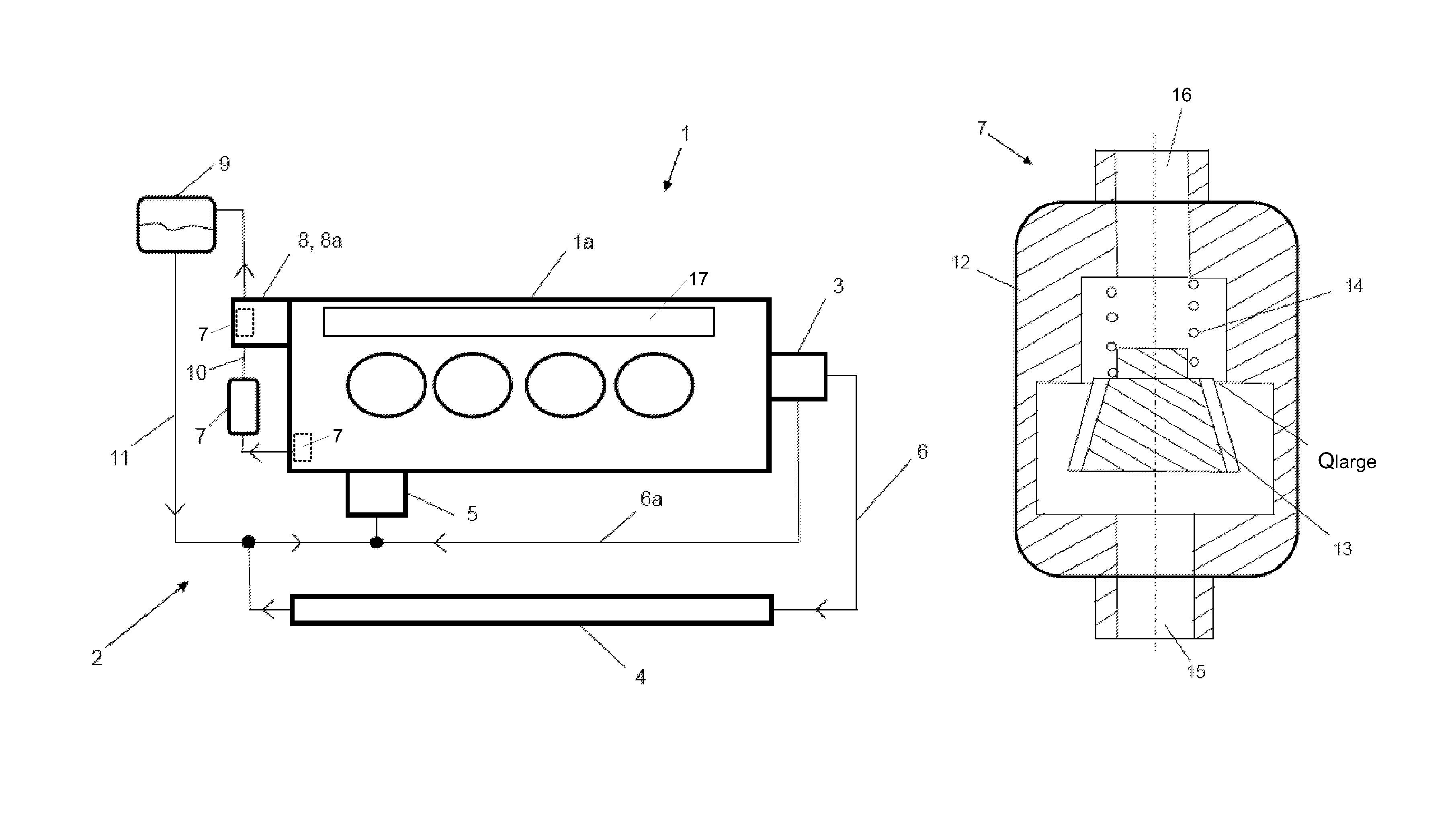
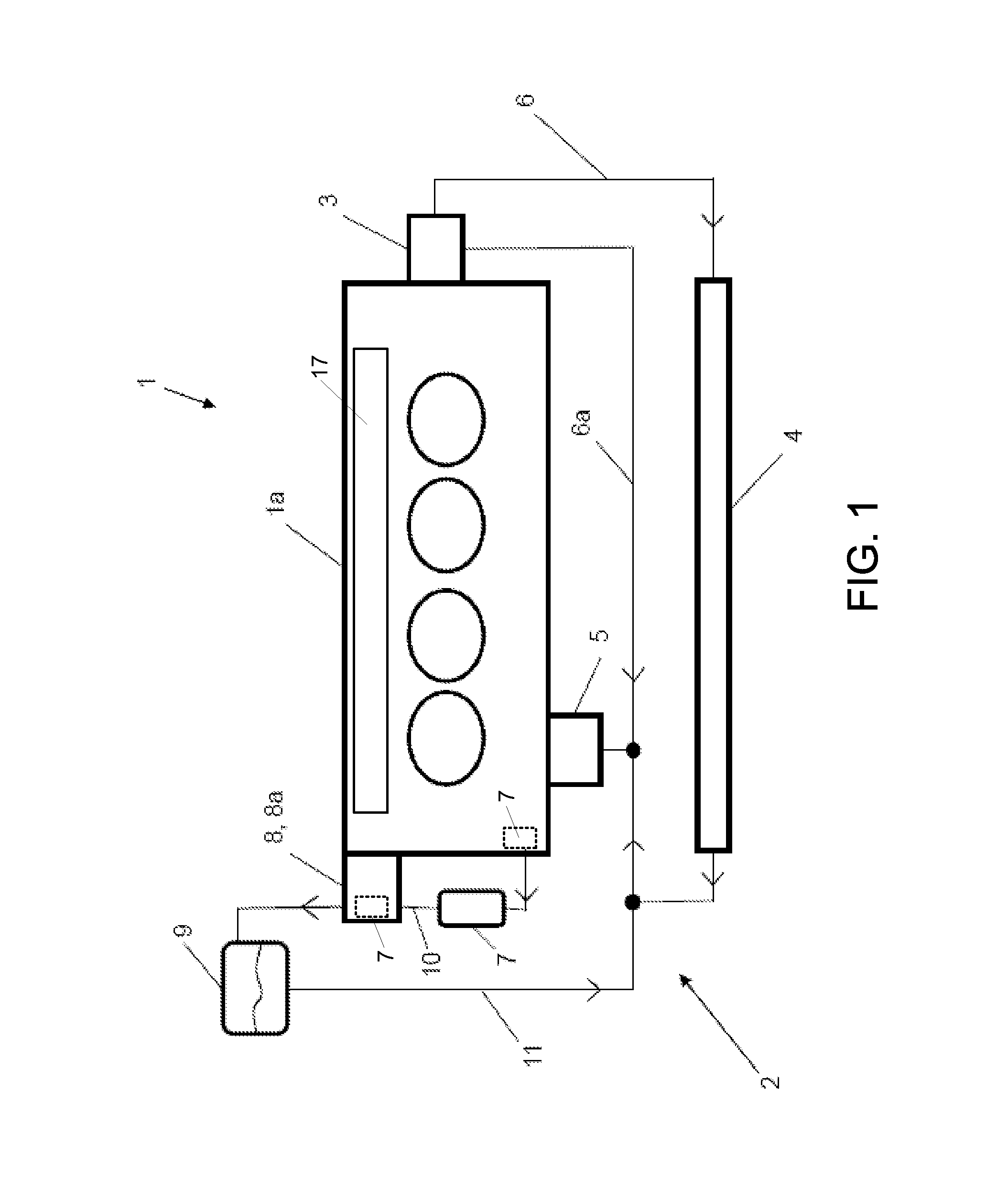
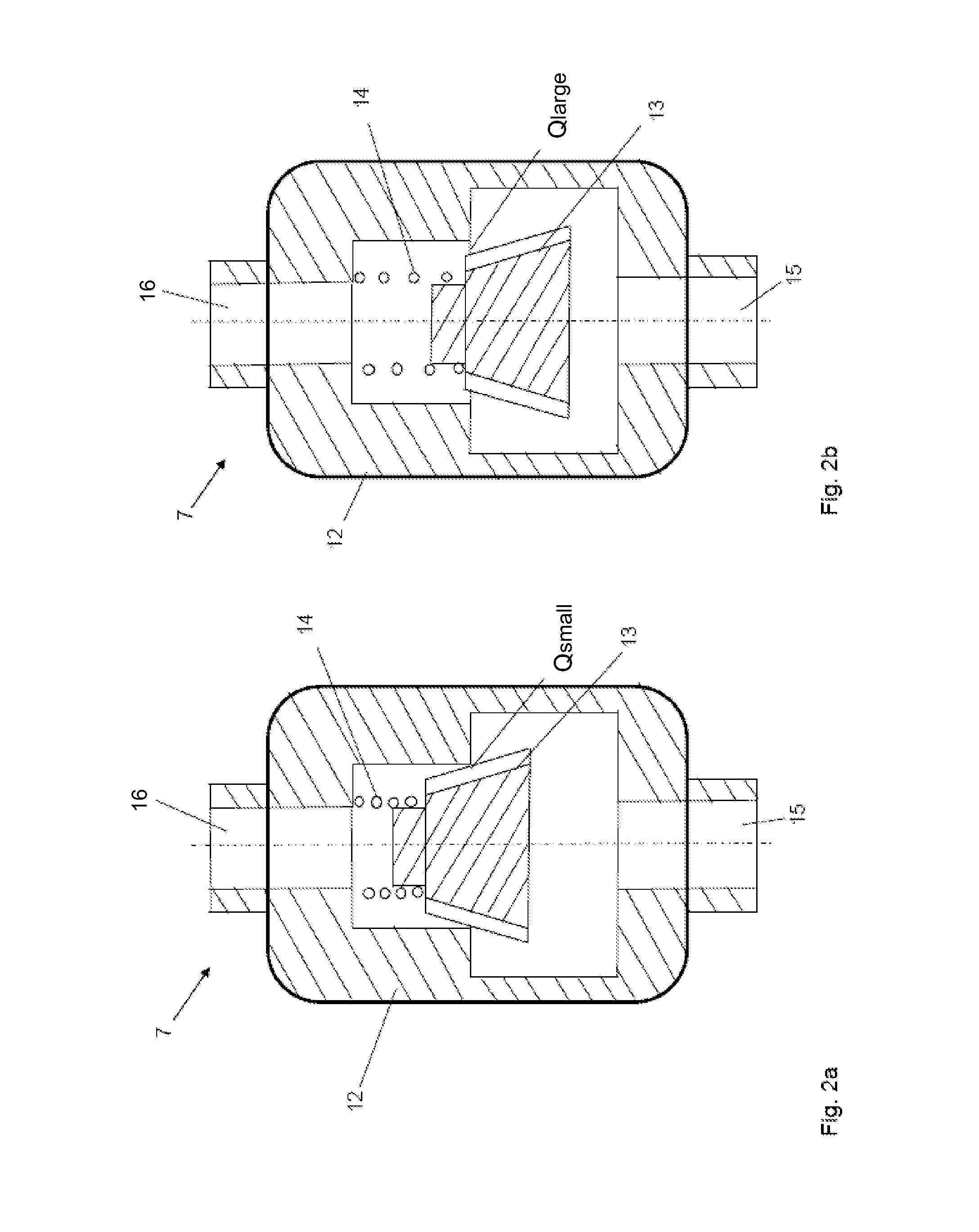
[0033]In order to provide coolant to an engine component on demand, even after shut down of the engine, a pressure-sensitive valve may be arranged between a coolant pump and the engine component to be cooled. Coolant may flow from the pump to the valve and the component during pump operation. Then, after the engine is shut down and the pump operation ceases, coolant may continue to flow due to the thermosiphon effect. The valve may move to a position having an increased cross-section during operation with low coolant pressure in order to provide an adequate amount of coolant to the engine component. The valve may be positioned in a connecting line of a cooling circuit of an engine upstream of a ventilation vessel.

[0034]The valve is arranged in the connecting line, wherein within the context of the present disclosure, the entire line section between the pump and the ventilation vessel is referred to as a connecting line, specifically regardless of whether the line leads through other...


PUM


Abstract

An engine comprises a cylinder head connected to a cylinder block; a cooling circuit including a pump, a heat exchanger, and a ventilation vessel; a liquid-cooled component, connected into the cooling circuit by a connecting line and arranged between the pump and the ventilation vessel, which is cooled when the engine is not in operation; and a valve which is self-controlling as a function of coolant pressure arranged in the connecting line between the pump and the ventilation vessel, the valve adjustable between a first working position having a first, relatively small cross section of the connecting line, and a second working position, having a second, relatively large cross section of the connecting line, the valve controlling coolant throughput, wherein when the engine is not in operation and coolant pressure is reduced, the valve is in the second working position to provide an enlarged flow cross section.

Description

CROSS REFERENCE TO RELATED APPLICATIONS[0001]The present application claims priority to German Patent Application 102012210320.1, filed on Jun. 19, 2012, the entire contents of which are hereby incorporated by reference for all purposes.FIELD[0002]The disclosure relates to a liquid-cooled internal combustion engine.BACKGROUND AND SUMMARY[0003]To form the individual cylinders of an internal combustion engine, the at least one cylinder head is connected, at an assembly end side, to a cylinder block. To hold the pistons or the cylinder liners, the cylinder block, which at least jointly forms the crankcase, has a corresponding number of cylinder bores. The pistons are guided in the cylinder liners in an axially movable fashion and form, together with the cylinder liners and the cylinder head, the combustion chambers of the internal combustion engine.[0004]To keep the thermal loading of the internal combustion engine within limits, it is increasingly common for a liquid-type cooling arra...

Claims


Application Information

Patent Timeline
Patent Type & Authority Patents(United States)
IPC IPC(8): F01P7/14F02F1/24F01P11/02
CPCF01P7/14F02F1/243F01P2060/12F01P2007/146F01P2031/30F01P11/0285
Inventor KAULEN, WILFRIEDNYIREGYHAZI, ZOLTAN
Owner FORD GLOBAL TECH LLC
Why Eureka
Try Eureka