Magnesium roll mill

a rolling mill and magnetic technology, applied in forging/pressing/hammering apparatus, heating/cooling devices, furnaces, etc., can solve the problems of limiting the maximum slab size, limiting the deformation ability of metal, and prohibitively expensive final sheets for consumer applications, etc., to improve the formability of rolled sheets and good quality surfaces

Active Publication Date: 2016-02-02
DANIELI & CO
View PDF20 Cites 8 Cited by
  • Summary
  • Abstract
  • Description
  • Claims
  • Application Information

AI Technical Summary

Benefits of technology

[0006]The magnesium rolling mill of the present invention provides an industrial rolling process that not only economically reduces the cast coils to the final gauge required by consumer products, but also modifies the microstructure of the as-cast magnesium to improve the formability of the rolled sheet, while maintaining a good quality surface that requires minimal treatment after rolling. Twin roll casting provides the great advantage of producing very large coils at the same gauge as the coiling gauge from a reversing mill.
[0007]The magnesium rolling mill of the present invention consists of a reversing mill, two opposite side hot coilers in possible combination of hot roller tables, material handling equipment and accessories. Magnesium product in the form of plates or coils are reciprocated through the mill until proper temperature is reached and the proper final thickness is obtained without deteriorating the quality of the configuration of the magnesium alloy final product.
[0008]The magnesium rolling mill of the present invention provides for rolling multiple passes of the magnesium sheet after the sheet has been brought to an elevated temperature typically between 250° C. and 350° C. The mill provides for intermediate annealing to re-soften the material structure. The mill includes the capability to roll with asymmetrical work roll speeds to introduce more mechanical work and heat into the roll bite and therefore reduce the basal plane texture of the HCP crystal structure of the magnesium thereby improving ductility and low-temperature formability of the rolled strip. The mill of the present invention has the capability to increase rolling speed for overall production capability and to allow a faster deformation speed. The mill includes a work roll diameter that balances the requirement to minimize the length of contact with the magnesium strip being deformed while simultaneously having sufficient torsional rigidity and strength to resist the loads created by the asymmetric rolling condition. The mill has a high speed hydraulic gap correction system capable of working in pressure or position control to accurately control the as-rolled gauge of the magnesium alloy. The mill provides for a higher reduction per pass to achieve better grain refinement and improve the general mechanical properties of the rolled strip. The mill includes high force actuators to provide work roll mechanical bending for strip shape correction and includes a coil to coil processing as well as plate to plate or plate to coil processing.
[0011]The mill further can include strip guiding and heating system for rolling sheet / plates rather than coils. In this mode of operation strip guides are used to bridge the coil boxes. A strip cooling system prior to final coiling at rewind is included to prevent gain growth during slow cooling of the coil. The mill includes a heavy duty drive system with possible gear shift for higher torque for asymmetrical rolling. The mill includes heated work rolls to minimize strip temperature loses when contacting the rolls during casting.

Problems solved by technology

Until recently, all magnesium sheet was made by hot rolling small ingots and the costs associated with the reheating operation to maintain the metal at rolling temperatures and the small coil sizes made the final sheet prohibitively expensive for consumer applications.
In the case of magnesium and magnesium sheet alloys, the HCP crystal structure of the metal limits its deformation abilities at lower temperatures.
Handling and reheating oven constraints limited the maximum slab size and traditionally made magnesium sheet production virtually a sheet-by-sheet operation.
This was a very labor and energy intensive, inefficient method of production and contributed to the high cost of magnesium sheet.
Conventional rolling processes can only produce small coil sizes because as the ingot is rolled, it gets longer and thinner, which increases the surface area, and therefore loses heat rapidly and gets too cool to roll any further.
It is not economical to off-line reheat long sections of rolled slab.

Method used


Image

  • Magnesium roll mill
  • Magnesium roll mill
  • Magnesium roll mill

Examples


Embodiment Construction

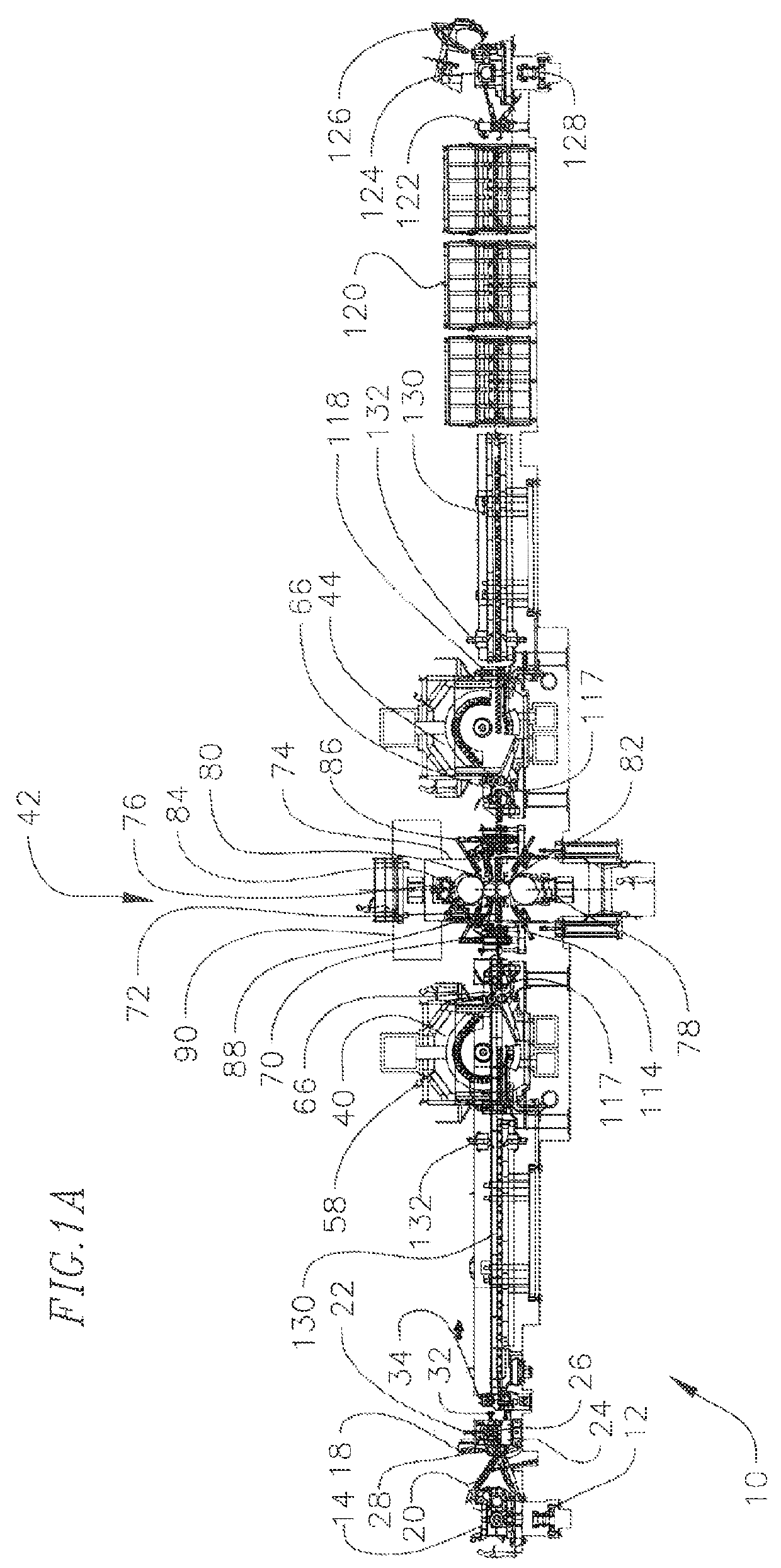
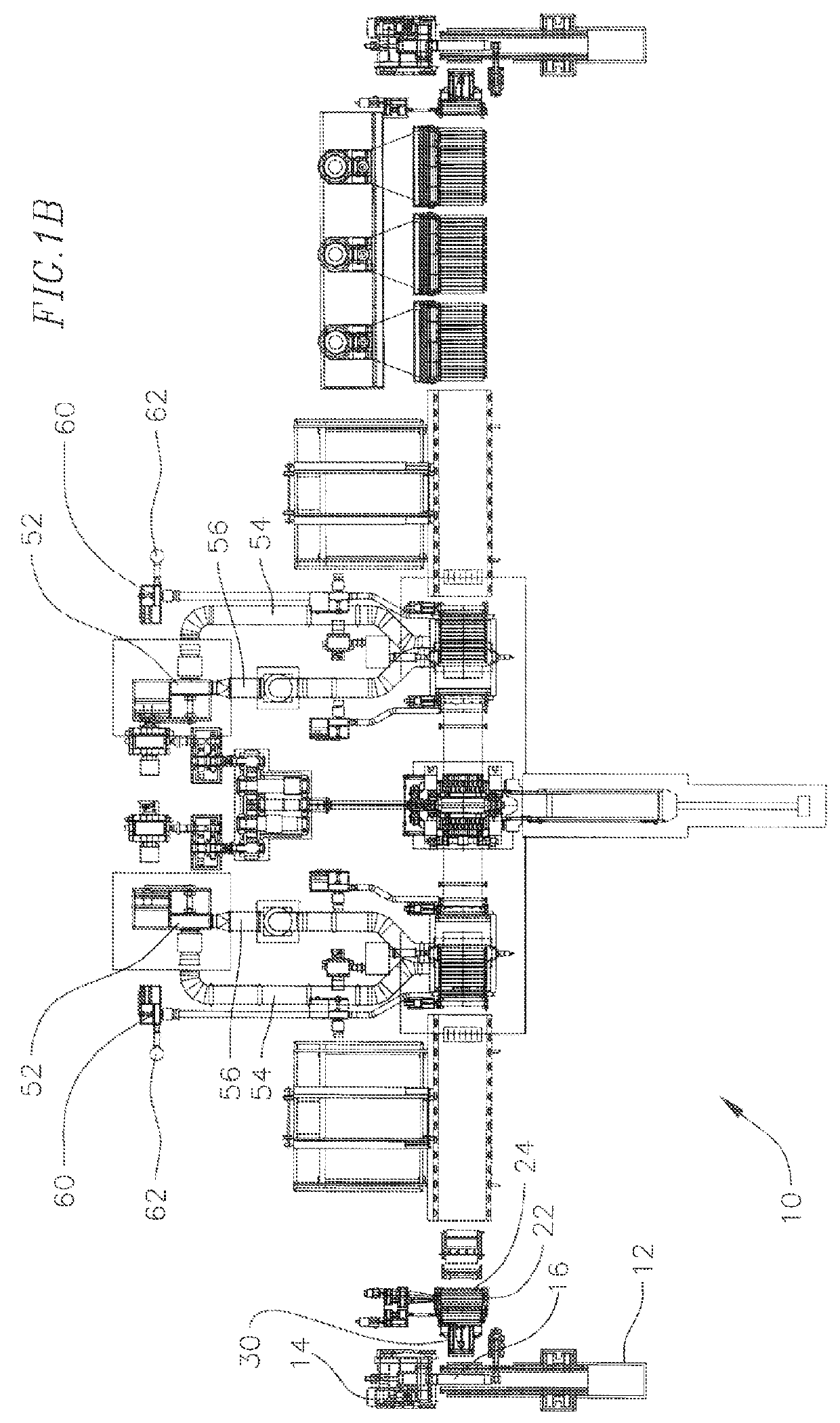
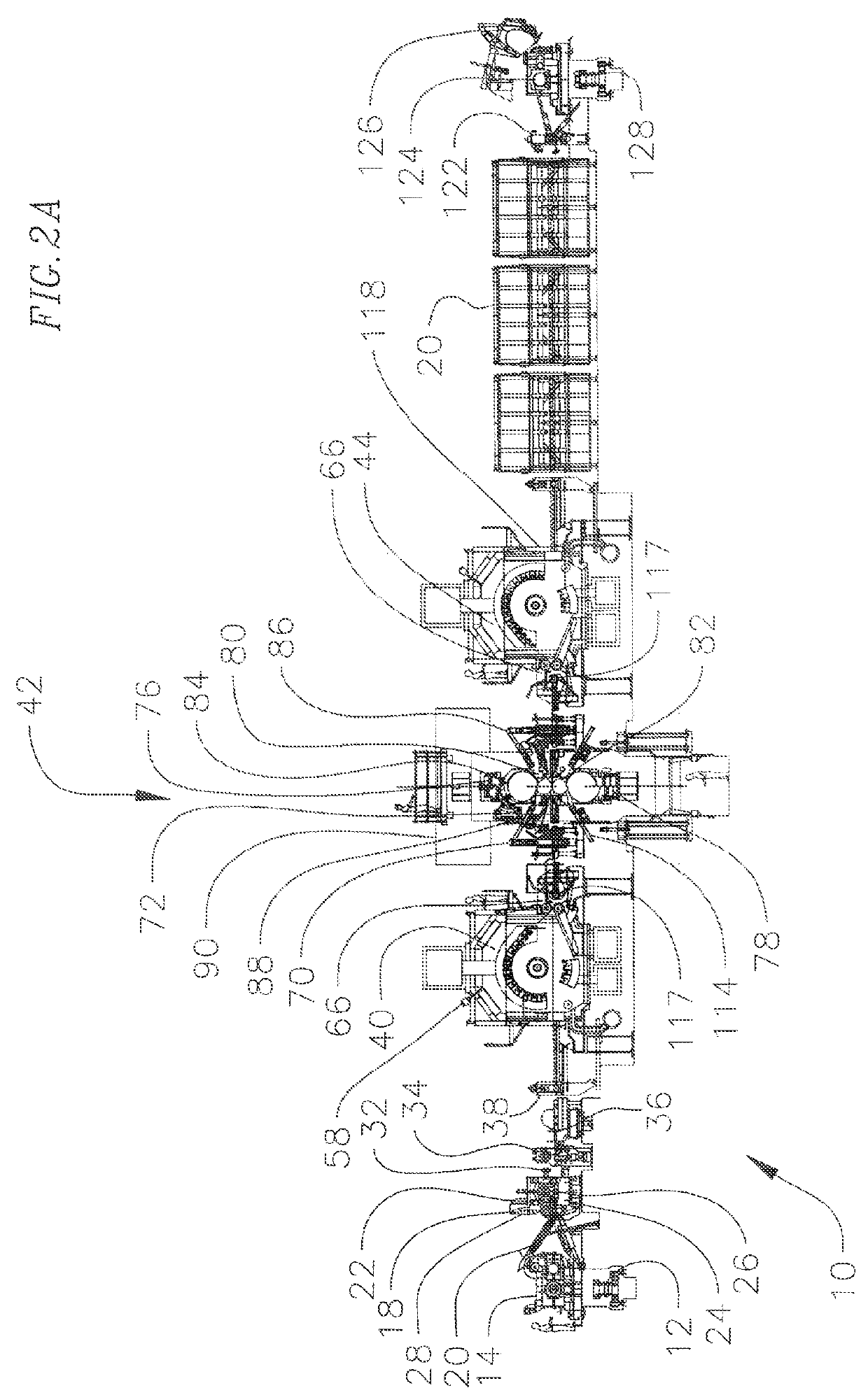
[0023]Referring to FIGS. 1A and 1B, an exemplary magnesium rolling mill 10 of the present invention is illustrated. The magnesium rolling mill 10 is a plate or coil rolling mill having independent pay off reel and unloading or rewind reels. The mill 10 includes an entry coil car 12 to receive a warm or cold magnesium coil from storage which loads it to a pay off reel 14. From a storage and cooling area, the coils to be rolled are loaded onto coil storage saddles using an overhead crane. The coil saddles straddle a coil car pit. The coil car 12 travels perpendicularly to the rolling direction to collect the coil from the coil storage saddles. The coil is picked up by the coil car, and traversed to the pay off reel 14. The coil car moves by a hydraulic motor and lifts the coil by a hydraulic cylinder. Laser sensors are used to monitor the lift and trends verse position of the coil car in order to automate the coil handling cycle. The coil car runs on rails.

[0024]The pay off reel 14 ha...


PUM

PropertyMeasurementUnit
temperatureaaaaaaaaaa
thickaaaaaaaaaa

Abstract

A magnesium hot rolling mill system including a rolling mill having at least two work rolls for rolling of magnesium sheet or plate, a hot coiler positioned on either side of the rolling mill for heating and maintaining a desired temperature of the magnesium sheet or plate, active thermal roller tables, a mill drive system for independently driving the work rolls for asymmetrical rolling of the magnesium sheet and a warm coil loading and payoff station.

Description

CROSS-REFERENCE TO RELATED APPLICATION(S)[0001]This Application claims priority to U.S. Provisional Application No. 61 / 451,961, filed Mar. 11, 2011, the contents of which are incorporated herein by reference.BACKGROUND OF THE INVENTION[0002]This invention relates to magnesium sheet, and more particularly to an apparatus and method for producing magnesium sheet by roll milling.[0003]The demand for personal electronics, fuel efficient light weight vehicles and other consumer products has driven the demand for competitively priced lightweight materials with a high specific strength and specific stiffness. In recent years magnesium alloy die castings have successfully been used in many applications, but further weight reductions have required the use of wrought magnesium sheet.[0004]Magnesium is a metal with a Hexagonal Close Packed (HCP) crystal structure that has very limited plasticity at room temperature. Until recently, all magnesium sheet was made by hot rolling small ingots and t...

Claims


Application Information

Patent Timeline
Patent Type & Authority Patents(United States)
IPC IPC(8): B21B3/00B21B1/34C21D9/68B21C49/00B21B1/36B21B35/04B21B45/00B21B15/00B21B27/08
CPCB21B3/00B21B1/34B21C49/00C21D9/68B21B1/36B21B35/04B21B45/004B21B2015/0057B21B2015/0064B21B2027/086B21B2265/24
Inventor PASSONI, ROBERTOROMANOWSKI, CHRISTOPHER A.
Owner DANIELI & CO
Why Eureka
Try Eureka