End seal with insert for chambered doctor blade assembly

a technology of end seals and inserts, which is applied in the direction of electrographic process equipment, instruments, printing, etc., can solve the problems of premature wear, ink leakage almost immediately, and the normal life expectancy of the seal is shortened considerably, so as to prolong the operational life improve the structural integrity of the end seal, and improve the sealing properties

Active Publication Date: 2016-02-02
FOLEY ANTHONY
View PDF4 Cites 2 Cited by
  • Summary
  • Abstract
  • Description
  • Claims
  • Application Information

AI Technical Summary

Benefits of technology

[0008]The present invention addresses the above described problems with prior art end seals by providing an end seal for an enclosed doctor blade assembly with the end seal having an abrasion resistant insert which improves the structural integrity of the end seal while also exhibiting good sealing properties and extended end seal operational life. The present invention addresses the problems of prior art end seals by providing an end seal for removable attachment to a doctor blade assembly. The end seal comprises a seal body having a bottom wall, opposite first and second sidewalls and a top edge configured to include a radius adapted to align with and seal against a roller surface.
[0010]In another embodiment, more than one insert may be provided in the seal body in spaced, parallel relation to one another (e.g., two, three, four or more inserts). The provision of more than one insert provides added protection against leakage of fluid past the end seal in that if the first insert closest to the reservoir is compromised and fluid leaks past this first insert, the second insert which is adjacent the first insert will act as a back-up barrier to prevent further fluid leakage past the second insert, and so on should the second insert fail with end seals having more than two inserts.

Problems solved by technology

Traditional doctor blade assembly end seals are manufactured from compressible foam and rubber materials which are very susceptible to uncontrolled deformation and dislodgement from the ideal operating position relative to the surface of the anilox roller, particularly when exposed to changes in the internal operating pressure of the enclosed fluid reservoir during normal operation, as well as the inherent mechanical drag applied by the rotation of the anilox roller, especially at elevated press speeds.
Once dislodged from the correct operating position the normal life expectancy of the seal is shortened considerably and ink leakage starts almost immediately.
Even if such a seal is not completely dislodged from the fluid reservoir frame, even minor unintended deformation or seal movement within the frame immediately leads to premature wear and some degree of unwanted leaking of the ink or other fluid from within the enclosed ink reservoir.
There is also excessive cost associated with the wasted ink as well as additional cleaning of the machine and various press components that are exposed to the leaking ink.
As such, the end seals are exposed to significant abrasive wear as the anilox roller rotates, particularly at very high speeds which result in a proportional increase in the COF (coefficient of friction) and mechanical stress applied to the seals.
Thus, as machine speeds have continued to increase, the industry has seen the prior art seals wearing out or otherwise failing faster than ever before.
Besides being subjected to abrasive wear, the end seals are also exposed to various levels of hydraulic pressure applied by the reservoir fluids (e.g., the printing ink and cleaning solutions) that are pumped into and out of the reservoir during normal operation of the press.
This rapid wear of the seals results in a considerable decrease in productivity due to the press operator having to frequently stop the printing press to replace worn, dislodged or leaking end seals in each of the print stations.
This change in internal pressure within the enclosed ink reservoir has been known to dislodge one or both the end seals from their ideal operating position, leaving the seals incorrectly oriented relative to the surface of the anilox roller.
If the machine is then operated with the end seals in an incorrect orientation relative to the curved surface of the anilox roller, the end seal wears rapidly (similar to having unbalanced tires on a car) which, if not caught by the operator, results in a loss of intimate contact with the surface of the anilox roller which in turn allows ink to enter the area where the seal makes contact with the surface of the anilox roller.
Once the printing ink enters this area (between the surface of the seal facing the roller and the anilox roller) the ink starts to dry which then adds to the rate of abrasive wear on the seal.
Compounding the problem is that the new gearless press technology runs at 2-3 times the production speed of conventional geared presses.

Method used


Image

  • End seal with insert for chambered doctor blade assembly
  • End seal with insert for chambered doctor blade assembly
  • End seal with insert for chambered doctor blade assembly

Examples


Embodiment Construction

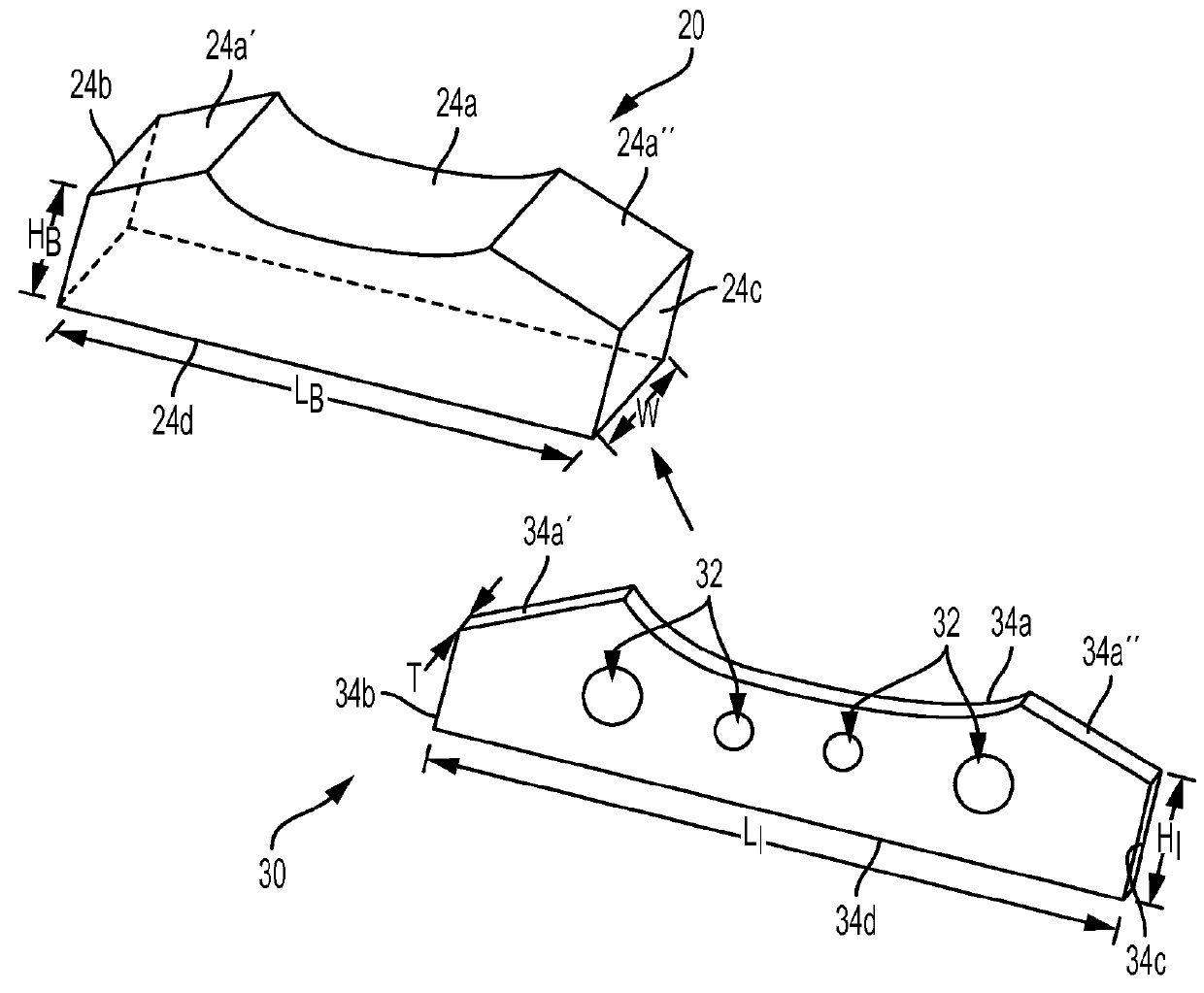
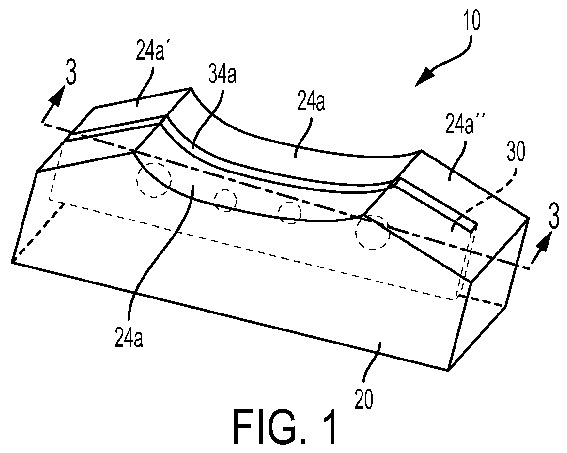
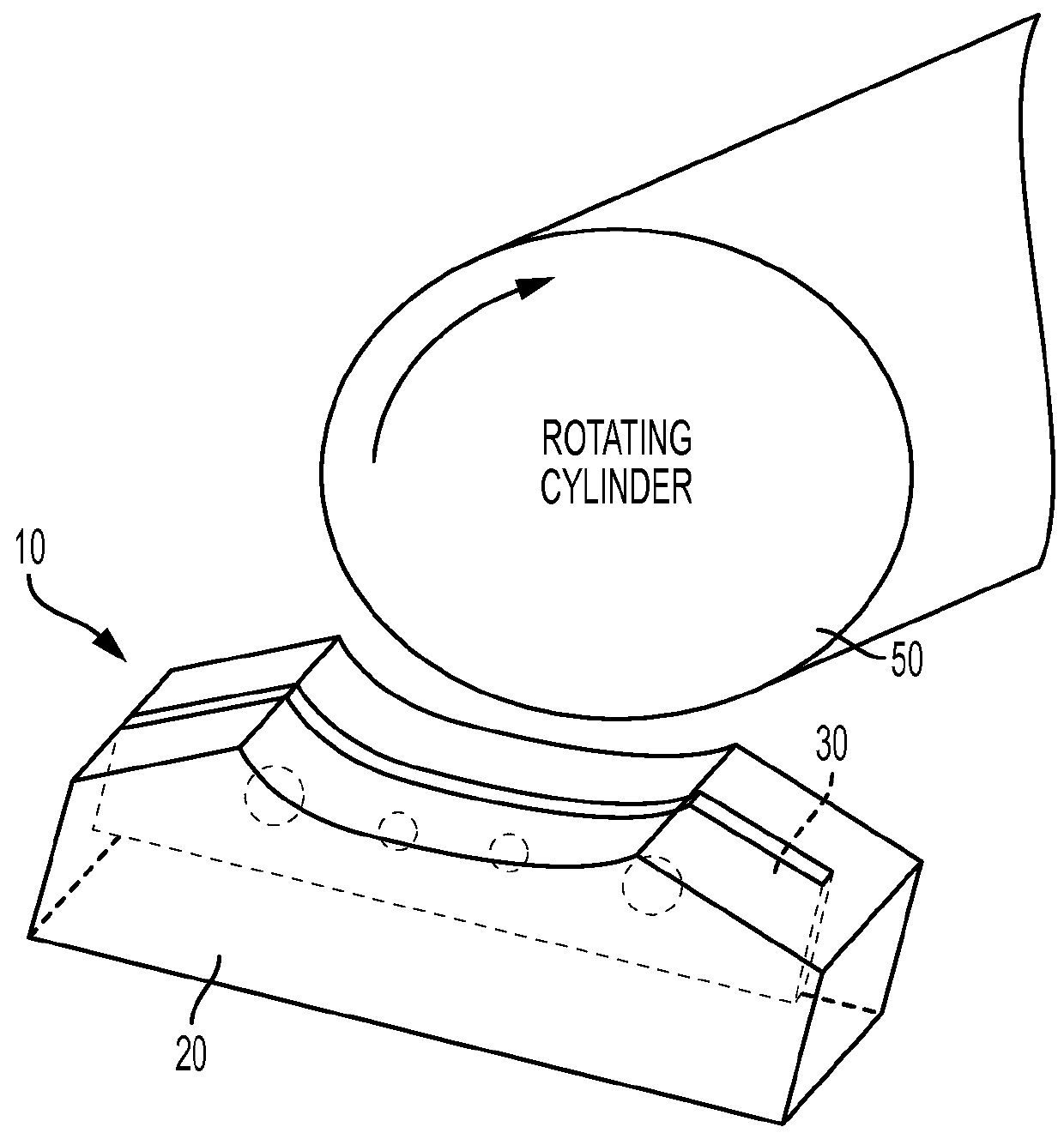
[0019]Referring now to the drawing, there is seen in FIGS. 1-4 an embodiment of the inventive end seal designated generally by the reference numeral 10. Seal 10 includes a seal body 20 adapted to carry an integral abrasion resistant insert 30. Seal body 20 is preferably formed from a from a rigid yet resilient material (e.g., about 25-90 Durometer Shore A, more preferably about 60-80 Shore A, and yet more preferably about 70 Shore A) which may be injection or compression molded from an appropriate material such as, for example, thermoplastic materials or thermoset materials, EPDM rubber, Buna-N rubber, Natural Rubber, SBR Rubber, Viton, of a rubber compound that has been blended with performance enhancing additives having like characteristics, although other manufacturing processes are of course possible (e.g., cast molding, machining, SLA, vulcanization, vacuum molding, rapid prototyping, mechanical die cutting, water jet cutting, etc.). For the sake of simplicity, the material com...


PUM


Abstract

An end seal for removable attachment to a doctor blade assembly is provided. The end seal comprises a seal body having a bottom wall, opposite first and second sidewalls and a top edge configured to include a radius adapted to seal against a roller surface. At least one abrasion resistant insert is integrally secured within the seal body. The insert includes a bottom wall, opposite first and second sidewalls and a top edge configured to coincide with the body top edge so as to seal against the roller surface. The abrasion resistant insert may further include one or more holes wherein the seal body impregnates the holes. One or both of the opposite first and second insert sidewalls and / or the insert bottom wall may reside within and be encapsulated by the seal body. The abrasion resistant insert may be constructed of polytetrafluoroethylene, a perfluoroalkoxy alkane or fluorinated ethylene propylene.

Description

BACKGROUND OF THE INVENTION[0001]The present invention generally relates to doctor blade assemblies which define an enclosed fluid reservoir for applying fluid to a rotating roller, and more particularly relates to an abrasion resistant end seal used to seal the opposite ends of the fluid reservoir, the end seal including an integral abrasion resistant insert which engages with the roller and where the insert may serve as a rotary doctor / metering blade.[0002]Enclosed doctor blade assemblies are used extensively in machinery utilizing a rotating roller that picks up fluid from a reservoir and deposits the fluid onto another surface located opposite the doctor blade assembly. Examples of such machinery include rotary printing units such as flexographic printing machines. Such enclosed doctor blade assemblies can also be utilized for the application of varnish, adhesives and various specialty coatings, for example. In a flexographic printing station, the enclosed doctor blade assembly ...

Claims


Application Information

Patent Timeline
Patent Type & Authority Patents(United States)
IPC IPC(8): G03G15/08B41F31/02
CPCG03G15/0817B41F31/027G03G15/0898
Inventor FOLEY, ANTHONY
Owner FOLEY ANTHONY
Why Eureka
Try Eureka