Magnetic head, magnetic recording method and apparatus for controlling magnetic head with spin torque oscillator in a disk drive

a magnetic recording method and magnetic recording technology, applied in the field of magnetic recording methods and apparatuses for controlling the magnetic head with spin torque oscillator in the disk drive, can solve the problems of reducing the anisotropic energy that would maintain the magnetization state, the recorded magnetization state is more readily disturbed by thermal fluctuation, and the practical limit of simply extending current technology, etc., to achieve the effect of reducing the curvature of the recording edge, reducing the blurring or the curvatur

Active Publication Date: 2016-03-01
HITACHI LTD
View PDF33 Cites 82 Cited by
  • Summary
  • Abstract
  • Description
  • Claims
  • Application Information

AI Technical Summary

Benefits of technology

[0021]An increase in recording density may be achieved in the magnetic recording apparatus by two methods: one is to increase the linear recording density in the direction of travel of the magnetic head; and the other is to increase the track density in the track width direction. The microwave assisted recording differs greatly from thermal assisted recording in that the track density can be magnetically determined as described above. In fact, the discussion in Non-patent Document 3 indicates, through a LLG (Landau-Lifshitz-Gilbert) simulation, that a recording field from the STO is sharper and produces smaller blurring than a recording field from the main magnetic pole and is therefore more suitable for narrowing the track. Further, there is the advantage that the thickness of the STO element is smaller than the recording magnetic pole by approximately an order of magnitude, so that a narrow track pattern can be more easily formed. Thus, it was considered that narrow-track, high recording density magnetic recording can be implemented when the recorded track width can be determined by the STO of the main magnetic pole type magnetic pole structure. Accordingly, the present inventors conducted further studies with a view to achieving higher track density by microwave assisted recording with a main magnetic pole and magnetic shield type recording head (hereafter referred to as a “main magnetic pole type magnetic head”).
[0040]An object of the present invention is to provide a magnetic head such that high track density recording exceeding the trend of the related art is enabled for microwave assisted recording, and a high-capacity and highly reliable magnetic recording apparatus that enables high recording density of 1 Tb / in2 or more.
[0044]According to an embodiment, a recording track greatly narrower than the track width of the magnetic core can be recorded, so that a track density far higher than the track density according to related-art technology can be achieved, and a high recording density of 1 Tb / in2 or higher can be easily achieved.
[0045]Further, compared to a conventional head, the ring-type magnetic core according to an embodiment can produce a uniform and strong oscillation control magnetic field in the write gap portion substantially perpendicularly to the STO film. Thus, the STO disposed in the write gap can be caused to more stably oscillate such that a strong recording field necessary for recording a high coercive force perpendicular magnetic recording medium can be easily obtained. Further, the high-frequency magnetic field obtained from the high-frequency magnetic field oscillator in this way is sharp compared with the recording field from the recording magnetic pole. Thus, the recording blurring or the curvature of magnetization at the edge of the recording track can be decreased, the reading noise component from the recording track edge can be decreased, and thus a higher S / N than that with the microwave assist head of the conventional perpendicular head structure (main magnetic pole and magnetic shield structure) can be obtained.
[0046]In the magnetic recording apparatus according to an embodiment, the write current, clearance, and the STO current (voltage) may be adjusted adaptively during the assembly of the apparatus and, when there is an environment change or a transient phenomenon, these values may be adjusted by taking advantage of the feature of the embodiment that recording with only the recording field cannot be performed, so that the recorded track profile or the recording field distribution in the recorded track width direction can be adjusted. Thus, significantly improvements in the manufacturing yield of the apparatus and performance can be achieved by absorbing magnetic head manufacturing variations. Further, the robustness against an environment change, such as a temperature or atmospheric pressure change, or a transient phenomenon upon return from a recording / reproduction pause status can be significantly increased.
[0047]Thus, the second-generation microwave assisted recording head according to an embodiment can provide excellent performance compared with the first-generation microwave assist system of the conventional perpendicular head structure, so that the recording density, particularly the track density, can be greatly increased. Further, when combined with a magnetic head drive control apparatus, an evaluation / adjusting system, or manufacturing equipment related thereto, a high-capacity and highly reliable magnetic recording apparatus with a particularly high recording density, performance, manufacturing yield, and reliability can be provided.

Problems solved by technology

However, a decrease in the crystallographic grain of the perpendicular magnetic recording medium leads to a decrease in anisotropic energy that would maintain a magnetization state, so that the recorded magnetization state tends to be more readily disturbed by thermal fluctuation.
Thus, there is supposedly a practical limit to simply extending current technology in the era on the order of 1 Tb / in2, as discussed by Non-patent Document 1.
Developing a technology for overcoming the limit is a major problem in achieving an increase in recording density.
The ring-type longitudinal recording head that had been used for longitudinal magnetic recording, in which a ring-type (C-shaped) magnetic core is formed and recording is performed with a strong longitudinal recording field produced from a write gap of the magnetic core, was considered to be not suitable for increasing recording density for perpendicular magnetic recording due to a small write field gradient.

Method used


Image

  • Magnetic head, magnetic recording method and apparatus for controlling magnetic head with spin torque oscillator in a disk drive
  • Magnetic head, magnetic recording method and apparatus for controlling magnetic head with spin torque oscillator in a disk drive
  • Magnetic head, magnetic recording method and apparatus for controlling magnetic head with spin torque oscillator in a disk drive

Examples


first embodiment

[First Embodiment]

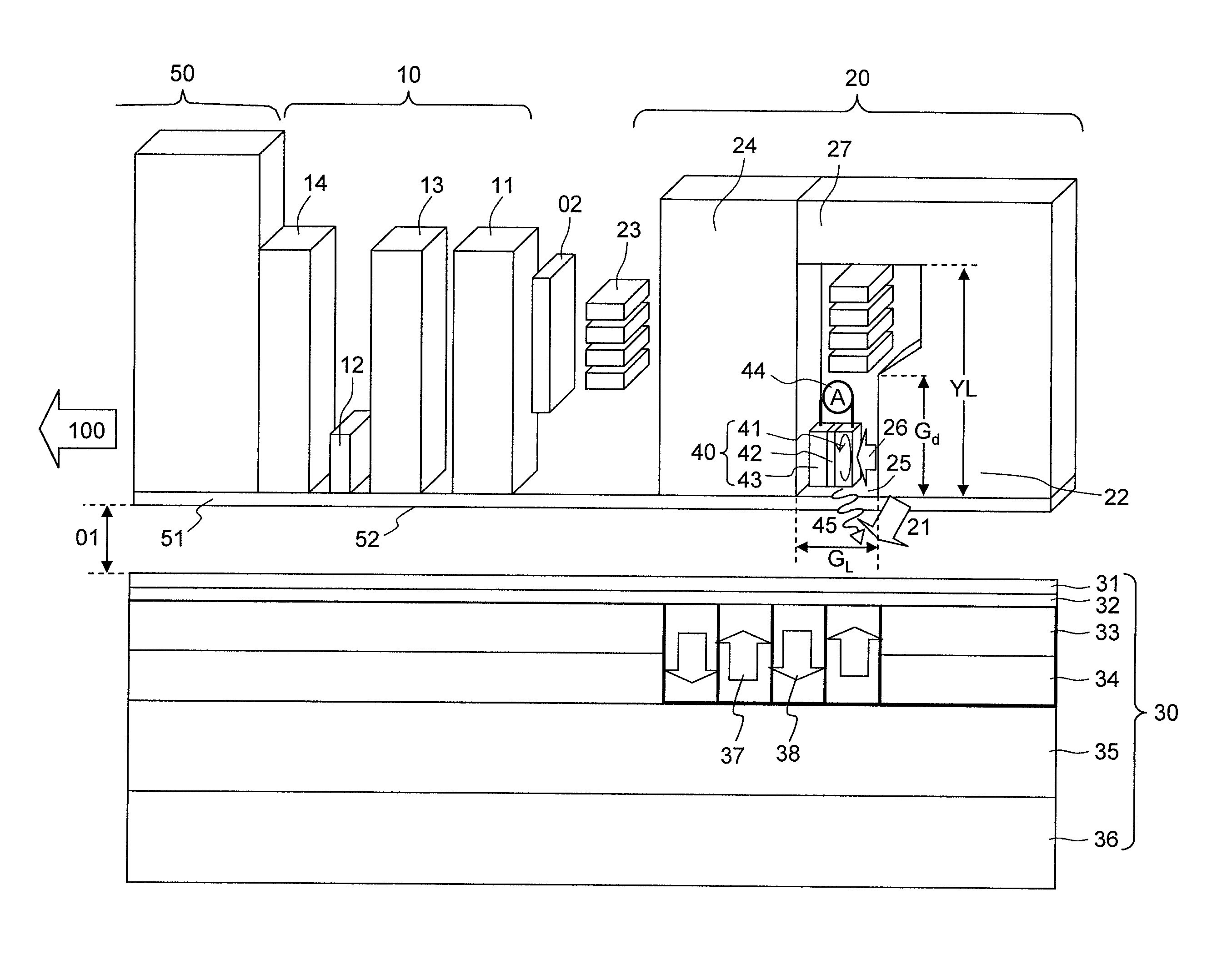
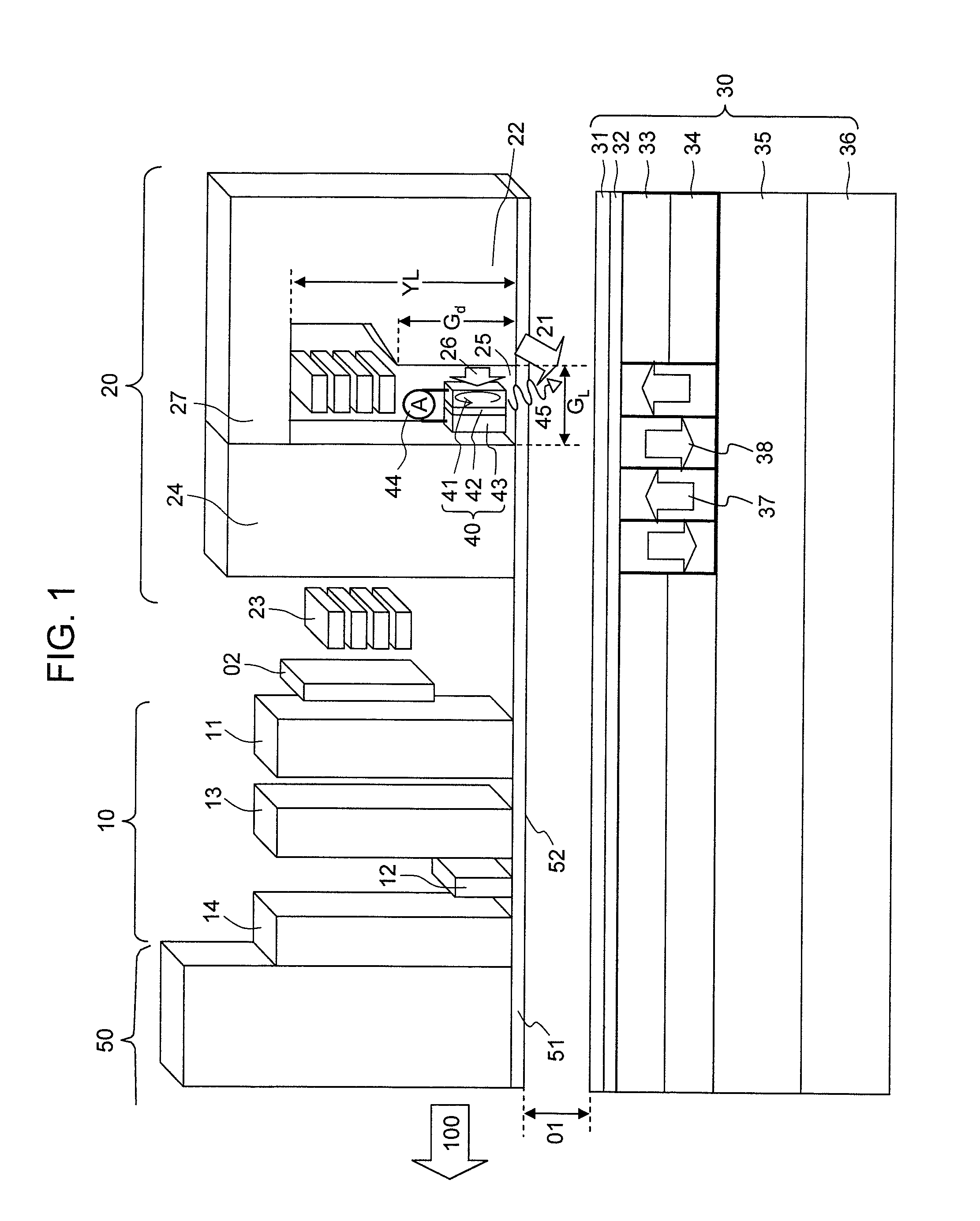
[0091]FIG. 1 is a schematic diagram of a perpendicular magnetic recording medium and a magnetic head according to an embodiment.

(Perpendicular Magnetic Recording Medium)

[0092]A perpendicular magnetic recording medium 30 includes a super-smooth and heat-resistant non-magnetic substrate 36 of glass, Si, plastics, or NiP plated Al, for example. The perpendicular magnetic recording medium 30 further includes, disposed on the substrate 36, a soft-magnetic underlayer 35 of FeCoTaZr and the like; first and second recording layers 34 and 33 of a magnetic film containing CoCrPt, a L12-Co3Pt base alloy, a L12-(CoCr)3Pt base alloy, a L11-Co50Pt50 base alloy, a m-D019 type Co80Pt20 base alloy, CoCrSiO2 / Pt, a CoB / Pd magnetic super-lattice, or L10 type FePt as a major constituent element, and an additive such as SiO2, TiO2, C, B, Ag, Cu, Au, Ni, Fe, Cr, Mn, or Pd which may be added as needed; an overcoat layer 32 of C or FCAC (Filtered Cathodic Arc Carbon), for example; and a lu...

second embodiment

[Second Embodiment]

[0121]In the present embodiment, a detailed example of the magnetic head according to the first embodiment will be described.

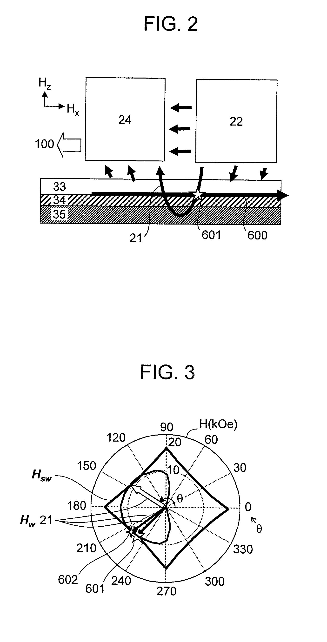
[0122]As described in the Summary with reference to FIG. 38, in the conventional magnetic head, the magnetization of the perpendicular magnetic recording medium is reversed immediately under the main magnetic pole, particularly in a region in the vicinity of the side of the main magnetic pole that is under the strong influence of the demagnetization of the field perpendicular magnetic recording medium such that recording takes place even only with the magnetic field from the main magnetic pole. As a result, the recorded track width is determined by the magnetic field width from the main magnetic pole, and desired narrow track magnetic recording cannot be performed even by microwave assisted magnetic recording. Thus, according to the present embodiment, attention is focused on important parameters of the perpendicular magnetic recording mediu...

third embodiment

[Third Embodiment]

[0156]According to the present embodiment, another magnetic head that provides a particularly strong high-frequency oscillation magnetic field will be described.

[0157]In order to generate a strong high-frequency magnetic field, it is preferable to increase particularly the saturation magnetic flux density and the film thickness while suppressing the development of a magnetic domain structure in the FGL. The present inventors conducted studies and have found that, as illustrated in FIG. 16, the development of the magnetic domain structure can be suppressed by layering the first and second FGLs 162 and 164 of a magnetic alloy with negative perpendicular magnetic anisotropy energy, such as Fe0.4CO0.6, Fe0.01Co0.99, or Co0.8Ir0.2; a Heusler alloy such as CoFeGe, CoMnGe, CoFeAl, CoFeSi, or CoMnSi; or a magnetic super-lattice such as Co / Fe, Co / Ir, Co / Ni, or CoFeGe / CoMnGe, in which the demagnetization field is also taken into consideration such that the magnetization tend...


PUM

PropertyMeasurementUnit
gap lengthaaaaaaaaaa
gap depthaaaaaaaaaa
gap depthaaaaaaaaaa

Abstract

A microwave assisted magnetic recording head includes a recording magnetic pole unit that produces a recording field for writing to a perpendicular magnetic recording medium, and a high-frequency magnetic field oscillator that produces a high-frequency magnetic field. The recording magnetic pole unit includes a magnetic core with a write gap portion at which a main recording field component is concentrated, and the high-frequency magnetic field oscillator is disposed in the write gap.

Description

CLAIM OF PRIORITY[0001]The present application claims priority from Japanese patent application JP 2012-045986 filed on Mar. 1, 2012, the content of which is hereby incorporated by reference into this application.BACKGROUND OF THE INVENTION[0002]1. Technical Field[0003]The embodiments discussed herein relate to a magnetic head with the function of inducing magnetization reversal by applying a high-frequency magnetic field to a perpendicular magnetic recording medium, a magnetic recording apparatus including the magnetic head, a magnetic head drive control apparatus, and a method for controlling the same.[0004]2. Related Art[0005]As a result of the evolution of the Internet environment and the increase in the number of data centers spurred by the increasingly widespread use of cloud computing, the amount of information that is generated is rapidly increasing. There seems no doubt that magnetic recording apparatuses, such as magnetic disk drives (HDD) that have the highest recording d...

Claims


Application Information

Patent Timeline
Patent Type & Authority Patents(United States)
IPC IPC(8): G11B21/02G11B27/36G11B5/31G11B13/04G11B5/127G11B5/02G11B5/23G11B5/00
CPCG11B13/04G11B5/1278G11B5/3146G11B5/23G11B2005/0024
Inventor SHIROISHI, YOSHIHIROFUKUDA, HIROSHIMIYAMOTO, HARUKAZUUSHIYAMA, JUNKOWATANABE, KATSUROHIRAYAMA, YOSHIYUKIIGARASHI, MASUKAZU
Owner HITACHI LTD
Why Eureka
Try Eureka