DNA and fingerprint authentication of mobile devices

a mobile device and fingerprint authentication technology, applied in the direction of transmission path division, eavesdropping prevention circuit, instruments, etc., can solve the problems of not being able to provide enhanced services to mobile users over a wide area, not having readily and widely accessible cellular and cellular interconnections, and many wide bandwidth applications and services that are rapidly evolving, so as to reduce the number of cables, eliminate the cumbersome connection of cables, and remove or minimize cables for patient monitoring

Active Publication Date: 2016-04-05
FEHER KAMILO
View PDF416 Cites 26 Cited by
  • Summary
  • Abstract
  • Description
  • Claims
  • Application Information

AI Technical Summary

Benefits of technology

[0094]Multiuse wireless communication applications, having extended coverage, improved performance, seamless interoperability, high speed operation, enhanced capacity, multipurpose, multi functionality, multi-mode and multi standard interoperability are highly desired. The current application discloses multiuse and or multipurpose applications, devices and systems, including systems for: position determination, location finding based services and applications, remote control, wireless, wired, cabled, internee, web based communication systems, communicator devices, radio frequency identification (RFID) systems with single or plurality of devices, emergency and other alarm systems, medical patient monitor-sensor devices, medical diagnostics devices, fingerprint identification, fingerprint control, interactive communication or control of communications and control systems, communications, broadcasting, teleinformatics and telemetry systems.
[0102]To remove or minimize cables for patient monitoring systems new architectures, structures and embodiments for multi mode, multi standard, non standardized wireless, wired, cabled, infrared, multiple “cascaded” switched and combined solutions and systems are presented in this disclosure. This include cascade of cellular i.e. GSM or GSM switched to CDMA systems, with short range wireless systems—one or multiple such as Wi-Fi, Bluetooth or other. Motivation for reducing the number of cables include, the desire to eliminate the cumbersome cables connected to the patient, facilitate the surgery, and facilitate and speed up the patient recovery-enabling the patient to move, exercise and improve the quality of life of the patient during surgery, recovery and post recovery monitoring and shorten emergency time response including a remote physician, nurse or other authorized health provider -in a reverse link to control-administer certain medical-pharmaceutical items, e.g. insulin or other; also to eliminate or reduce cable caused potentially harmful currents to the patient. The term reverse link means the link (signal flow) from the physician, nurse or other authorized health provider to the patient or patients medical device; the term forward link refers to the link from the patients medical device, e.g. from the cardiac stimulation device to the physician, nurse or other authorized health provider or health monitoring system.

Problems solved by technology

Hence, many wide bandwidth applications and services that are rapidly evolving, for example, on the Internet, have not to date readily and widely accessible cellular and cellular interconnections to mobile wireless users via wireless local area networks (WLAN) and / or other wideband networks.
However, the WLAN systems only provide short range coverage, are not widely deployed, or do not provide for user mobility and hence are not generally suitable of providing enhanced services for mobile users over a wide area.

Method used


Image

  • DNA and fingerprint authentication of mobile devices
  • DNA and fingerprint authentication of mobile devices
  • DNA and fingerprint authentication of mobile devices

Examples


Embodiment Construction

”.

BRIEF DESCRIPTION OF THE DRAWINGS

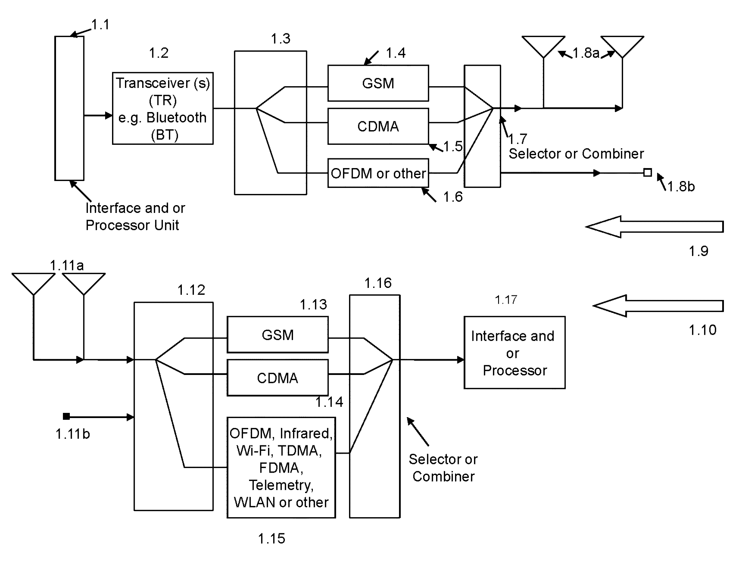
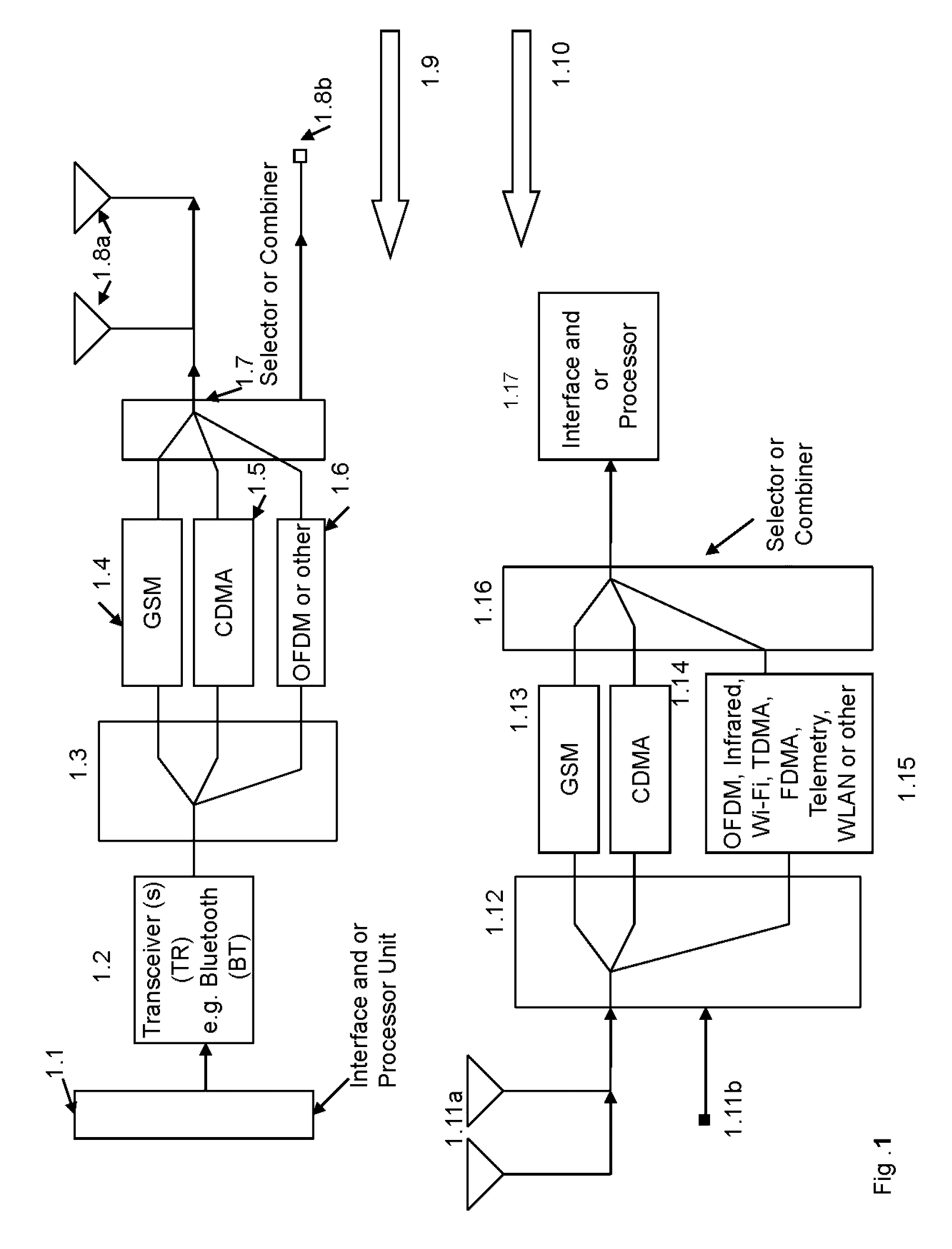
[0108]FIG. 1 shows implementation structures for single and or multiple communications systems, including single and or multiple location or position finder systems, Radio Frequency Identification Devices (RFID), medical diagnostics, emergency and remote control systems.

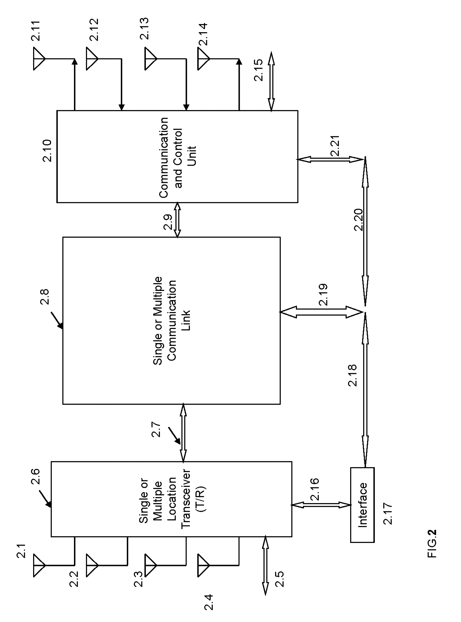
[0109]FIG. 2 is a structure of a multi mode location and multi-mode communication system, including wireless, wired (or cabled) and internet-web based connections with single or multiple communication links and or communication transceivers (T / R) and or communication and control units.

[0110]FIG. 3 is a structure of a system having single or a plurality of selectable Position Determining Entity (PDE), Base Station Controller (BSC), Terminal (Subscriber Unit) Base Station Transceiver Subsystem (BTS) devices.

[0111]FIG. 4 shows embodiments and structures for systems and networks containing Multiple Position Determining Entity (PDE), Base Station Controller (BSC) units, Terminal or Subsc...


PUM


Abstract

User generated and processed Deoxyribose Nucleic Acid (DNA) or fingerprint signal is used for authentication of a mobile device. A touch screen generated processed control signal is used for control of mobile device operated in a cellular system and a Wi-Fi network. The mobile device receives, demodulates and processes a location finder signal and provides processed location finder signal to an interface unit of mobile device. From a cellular base station the mobile device receives, demodulates and processes a modulated spread spectrum signal into a received, demodulated and processed baseband spread spectrum signal and processes, modulates and transmits in cascade the processed spread spectrum signal in a Wi-Fi system. The mobile device operates in a repeater mode. In one of the embodiments the spread spectrum signal uses a Code Division Multiple Access (CDMA) modulated signal and the Wi-Fi system uses OFDM modulated signal. The mobile device comprises step of processing a video signal into baseband in-phase and a quadrature-phase cross-correlated spread spectrum or Time Division Multiple Access (TDMA) signal. The video TDMA signal is modulated and transmitted as a Gaussian Minimum Shift Keying (GMSK) modulated signal in said cellular system and wherein said video signal comprises a three dimensional (3D) image.

Description

RELATED APPLICATIONS[0001]This application is a continuation application of U.S. utility patent application Ser. No. 14 / 180,361, entitled: “Cable Connected Mobile Video, Cellular and Wi-Fi Communications”, filed on Jun. 7, 2014 and scheduled to Issue as U.S. Pat. No. 8,849,313 on Sep. 30, 2014 and of U.S. utility patent application Ser. No. 13 / 735,031, filed on Jan. 7, 2013, entitled: “Cellular Video, Wi-Fi and Spread Spectrum System and Method” and now U.S. Pat. No. 8,688,142, issued on Apr. 1, 2014 and is a continuation application of U.S. utility patent application Ser. No. 13 / 492,273, filed on Aug. 8, 2013, entitled: “Digital Television (TV), Ship and Other Water Based Interactive Communication Methods”, and now U.S. Pat. No. 8,351,925, issued on Jan. 8, 2013 and is a continuation application of U.S. utility patent application Ser. No. 13 / 098,834, filed on May 2, 2011, entitled: “Mobile Television (TV), Internet, Cellular Systems and Wi-Fi Networks” and now U.S. Pat. No. 8,200,2...

Claims


Application Information

Patent Timeline
Patent Type & Authority Patents(United States)
IPC IPC(8): H04M1/66H04M1/68H04M1/673H04L29/06H04M1/725H04M3/16G06K9/00H04W12/06G06V40/13H04M1/72415
CPCG06K9/00013H04L63/0861H04M1/673H04M1/72533H04W12/06G06F21/32H04M1/67H04L63/0876H04W84/12H04W4/80H04W12/65G06V40/13H04W4/029H04M1/72415H04L5/0007H04L27/2017
Inventor FEHER, KAMILO
Owner FEHER KAMILO
Why Eureka
Try Eureka