
Air pollution control system and method

Active Publication Date: 2016-05-31
PARTICULATE MATTER SOLUTIONS
View PDF6 Cites 8 Cited by
  • Summary
  • Abstract
  • Description
  • Claims
  • Application Information

AI Technical Summary

Benefits of technology

The invention is a device that can be added to existing cooling tower units to improve air quality in urban areas. The device helps to reduce both large and small particulate matter, which can make the air we breathe in these areas poor. This is important because cooling towers are typically located in urban areas, and the device can help to make the air we breathe in these areas better. The device is easy to install, and uses the exhaust air from the cooling tower to help create cleaner air. This can save money on electricity costs, as the device makes the cooling fans work more efficiently. This invention aims to make a difference in air quality in urban areas and improve the quality of life for people who live there.

Problems solved by technology

Air pollution is a major global problem.
Although breathing-related illness and poor air quality are a global problem, some parts of the world are particularly affected.
Some of the worst air quality in the word exists in major metropolitan areas.
The size of particles is directly linked to their potential for causing health problems.
Once inhaled, these particles can affect the heart and lungs and cause serious health effects.
While industrially-generated pollutants (e.g. both gaseous pollutants such as CO2, as well as particulate pollutants) can be—and are often mandated to be—remediated at the source, the majority of particulate pollution sources do not lend themselves to this means of remediation.
This creates certain problems.
However, particulate pollutants such as smoke and asphalt dust are often generated over wide areas, which does not lend itself to easy control.
Particulate pollution is therefore dispersed in a huge volume of air.
Being able to capture and effectively channel this huge volume of polluted air through remediation means is a major problem.
However, unless the site is of gigantic proportions, it is very unlikely that such single-site remediation is going to be effective, simply because of the vast volumes of air involved, and because of the vagaries of air current and atmospheric conditions.
Moreover, building and operating such a large-scale remediation facility would be costly, which makes construction of such a facility with public funds politically challenging.
The high cost of such a facility (aside from the physical plant itself) results largely from the difficulty of finding enough suitable land in the right location in metropolitan areas, where land is at a premium, and therefore expensive.

Method used


Image

  • Air pollution control system and method
  • Air pollution control system and method
  • Air pollution control system and method

Examples


Embodiment Construction

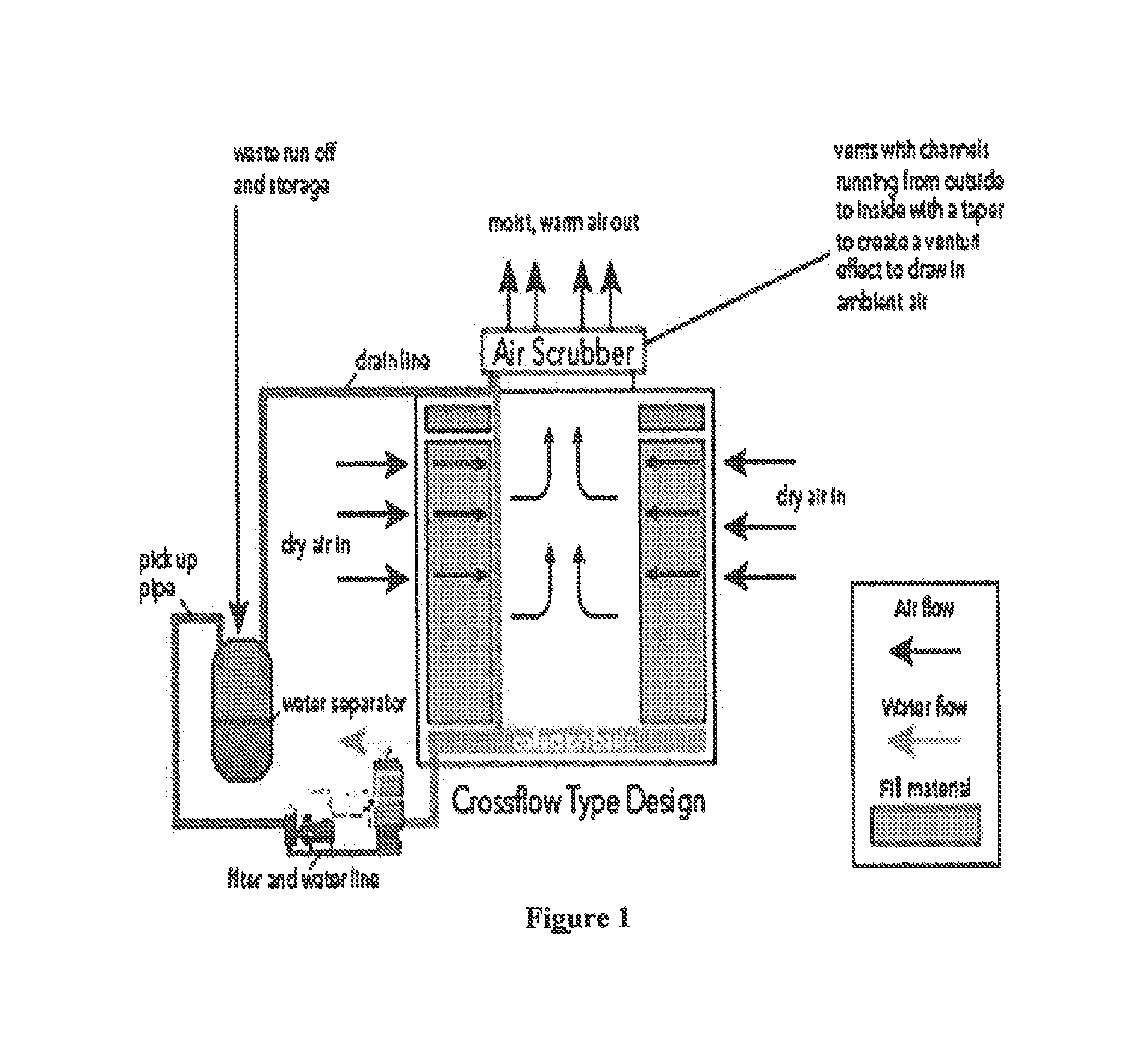
[0027]FIG. 1 shows an overall schematic of the system. Exhaust air flow from cooling tower fans passes through the air scrubber, which in turn draws ambient polluted air through the air scrubber. In a preferred embodiment, cooling water from the tower is used in a water-curtain method air purification, in which a misted water is sprayed at pressure into an air stream containing pollutants of the particulate matter variety.

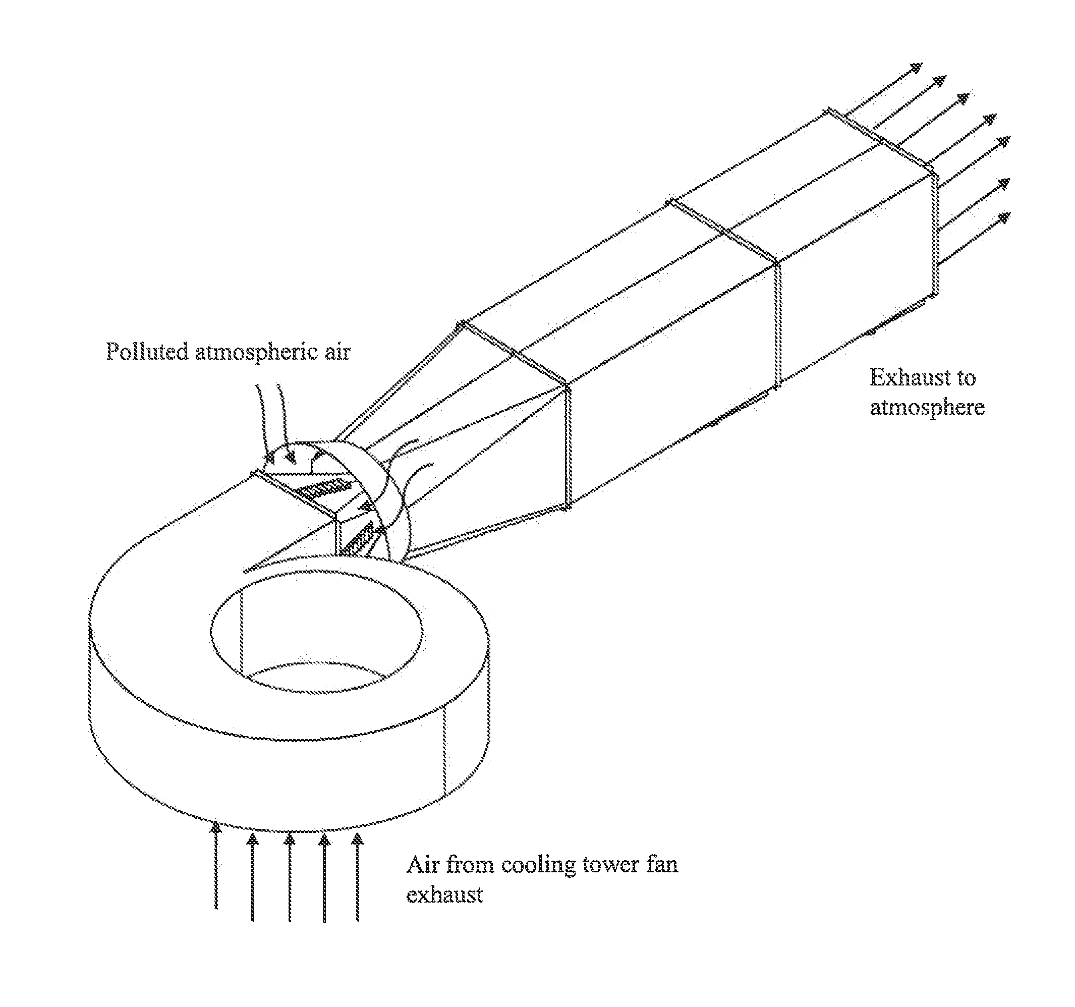
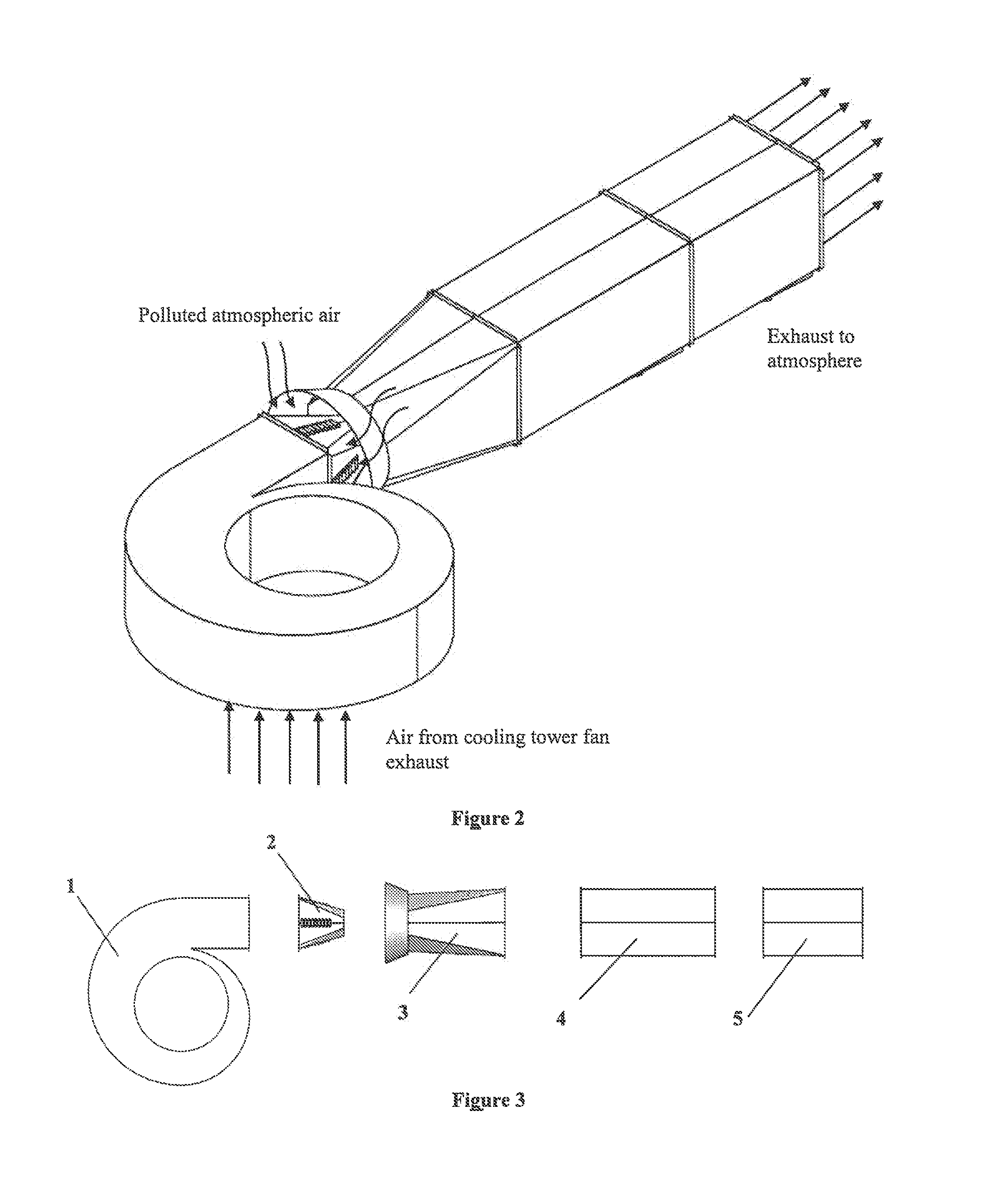
[0028]FIG. 2 shows one preferred embodiment of the invention. Exhaust airflow from the cooling tower is drawn into the generator section, which redirects and accelerates this exhaust airflow through a nozzle which, in conjunction with a venturi intake, creates a negative pressure region in the vicinity of the inlet side of venturi intake and draws atmospheric air into the scrubber section. FIG. 3 shows these components individually. The key components of the invention are the generator 1, nozzle 2, venturi intake 3, and scrubber ducts 4, 5.

[0029]FIG. 4a, 4b show bo...


PUM

PropertyMeasurementUnit
Areaaaaaaaaaaa

Abstract

A system for large-scale, distributed remediation of particulate air pollution using cooling towers is described herein. The system consists of a generator section which captures, redirects, and accelerates exhaust air from a cooling tower, a venturi inlet and nozzle, and at least one air scrubber stage.

Description

CROSS REFERENCE TO RELATED APPLICATIONS[0001]Not ApplicableSTATEMENT REGARDING FEDERALLY-SPONSORED RESEARCH OR DEVELOPMENT[0002]Not ApplicableBACKGROUND OF THE INVENTION[0003]Air pollution is a major global problem. Although breathing-related illness and poor air quality are a global problem, some parts of the world are particularly affected. Some of the worst air quality in the word exists in major metropolitan areas. Cities like Los Angeles, London, Mexico City, Beijing, and New Delhi are examples of major metropolitan areas with exceptionally poor air quality.[0004]An estimated 3.2 million people died prematurely in 2010 because of the poisonous effects of outdoor air pollution, according to the findings of an exhaustive study of global causes of death published in an issue of the British medical journal Lancet. Two-thirds of those killed by air pollution lived in Asia, where air quality continues to deteriorate.[0005]According to recent studies in the U.S., the total annual cost...

Claims


Application Information

Patent Timeline
IPC IPC(8): B01D47/00F24F13/02F28C1/00F24F7/00F24F8/117F24F8/133F24F8/142
CPCF24F13/02F24F7/00B01D47/00F28C1/00F28F25/00B01D47/06Y02A50/20Y02A50/2351F24F8/117Y02B30/70F24F8/133F24F8/142
Inventor ALLISON, III, ROBERT D.
Owner PARTICULATE MATTER SOLUTIONS
Learn More