Heater

a heater and heat sink technology, applied in the field of heaters, can solve the problems of high viscosity of lubricating fluid, inability to reduce friction enough, and deformation of the machine, so as to improve the adiabaticity of the heater, improve the sealability, and speed up the temperature of the lubricating fluid. the effect of raising the temperatur

Active Publication Date: 2016-07-05
NGK INSULATORS LTD
View PDF55 Cites 6 Cited by
  • Summary
  • Abstract
  • Description
  • Claims
  • Application Information

AI Technical Summary

Benefits of technology

[0026]A heater of the present invention is provided with a heater main body, a housing storing the heater main body therein, and a coating material covering at least a part of the heater main body. In a heater of the present invention, the coating material is a material containing at least one of ceramic and glass. In addition, the heater main body has a cylindrical honeycomb structural portion having partition walls separating and forming a plurality of cells extending from one end face to the other end face and functioning as passages for a lubricating fluid and a pair of electrode portions disposed on a side face of the honeycomb structural portion. The housing has an inflow port from which the lubricating fluid flows in and the outflow port from which the lubricating fluid having passed through the cells formed in the heater main body flows out. The housing stores the heater main body so as to cover the side face side of the heater main body. In a heater of the present invention, the partition walls of the honeycomb structural portion are of a material containing ceramic as the main component and produce heat by energization.
[0027]According to a heater of the present invention, temperature of the lubricating fluid can quickly be raised without excessively heating the lubricating fluid. In addition, even in the case that the size of the heater is small, the temperature of the lubricating fluid can quickly be raised.
[0028]Further, since a coating material is arranged so as to cover at least a part of the heater main body in at least a part between the heater main body and the housing, electric insulation between the heater main body and the housing can be obtained. In addition, the coating material functions also as a sealing layer between the heater main body and the housing. This enables to improve sealability between the heater main body and the housing. For example, by disposing the coating material, it plays a role of inhibiting the lubricating fluid as the target to be heated from leaking into the gap between the heater main body and the housing. Further, the aforementioned coating material functions also as an adiabatic layer of the heater main body. This enables to improve adiabaticity of the heater. For example, by disposing the aforementioned coating material, heat release to outside the housing carl be inhibited when heat is generated in the heater main body.

Problems solved by technology

When parts grind against each other in such a manner, abrasion or heat generation may be caused in the parts, and it may cause a defect in the machine.
However, in the case that such a lubricating fluid is at low temperature, the lubricating fluid has high viscosity.
As a result, there arises a problem of impossible sufficient reduction of the friction.
In addition, when the viscosity of the lubricating fluid becomes high, there arises a problem of impossible supply to an intended position.
However, when the lubricating fluid is excessively heated, a disadvantage of causing deterioration of the lubricating fluid is occurred.

Method used


Image

  • Heater
  • Heater
  • Heater

Examples


example 1

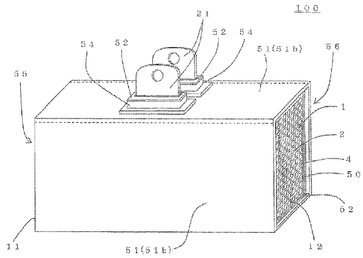
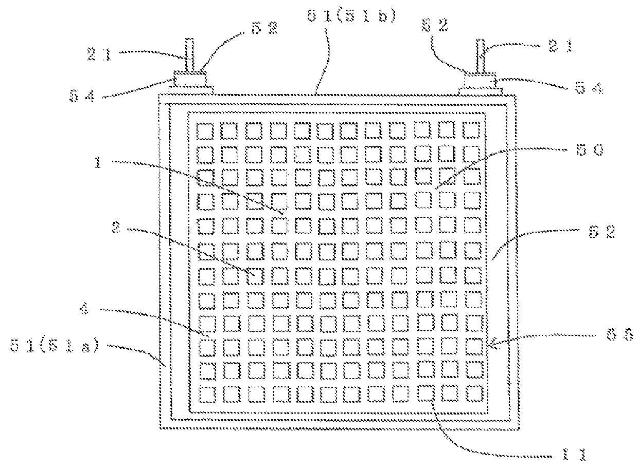
[0220]In the first place, a honeycomb structural portion containing Si composite SiC as the main component was manufactured. Specifically, a SiC powder, a metal Si powder, water, and organic binder were mixed together and kneaded to prepare a kneaded material. Next, the kneaded material was formed into a honeycomb shape to obtain a honeycomb formed body. Then, by firing the honeycomb formed body in an inert gas atmosphere, a honeycomb structural portion containing Si composite SiC as the main component was manufactured. The Si composite SiC honeycomb body had a porosity of 40%.

[0221]The shape of the honeycomb structural portion was cylindrical having square end faces. The length of one side of the square of the end faces was 38 mm. The length in the cell extension direction of the honeycomb structural portion was 50 mm. The thickness of the partition walls was 0.38 mm. The thickness of the outer peripheral wall was 0.38 mm. The cell density of the honeycomb structural portion was 47...

examples 2 to 6

[0235]There were manufactured heaters in the same manner as in Example 1 except that the material of the electrode portions, the structure of the electrode portions, and the structure of the housing were changed as shown in Table 1. By the use of the heaters, the energization heating test was performed in the same manner as in Example 1. The conversion efficiency (%) obtained from the results of the energization heating test is shown in Table 1. Table 1 shows the applied voltage (V), flow rate of the lubricating fluid passed through the heater (L / min), and initial temperature of the lubricating fluid (° C.) in the energization heating test.

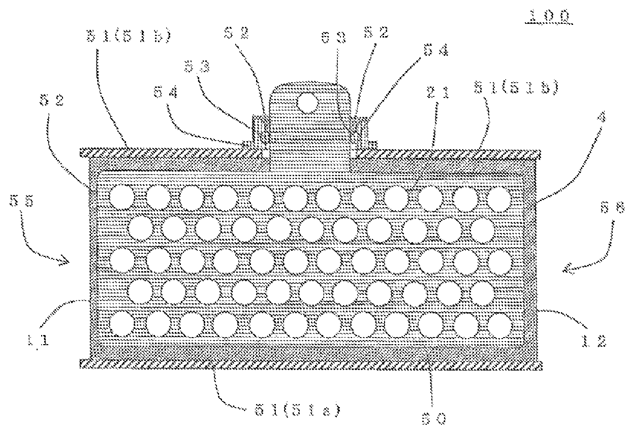
[0236]In Examples 3 to 6 where the “structure of housing” is as in FIG. 11, as the adiabatic material, a ceramic fiber sheet (Al2O3—SiO2 base) having a thickness of 5 mm was used. In addition, in Example 6, as the material for the electrode portions, pure metal copper (Cu) was used. Incidentally, also in the other Example where the “structure of h...

example 7

[0237]In Example 7, a heater was manufactured in the same method as in Example 3 except that a coating material was manufactured as follows. Here, the ceramic pore sealing material used in Example 1 was used as the coating material. As the ceramic pore sealing material, there was used a material containing tetraethyl orthosilicate (TEOS: Si(OC2H5)4), silane coupling agent, 2 propanol, 1 butanol, and water as the main component. In the first place, after homogenization by mixing again at below 100 rpm by the use of a ball mill before being used, it was coated on the outer peripheral portion of the heater main body by brush coating. The ceramic pore sealing material coated above was fired at 80° C. as preheating for inhibiting crack generation, then fired at 150° C., and further fired at 350° C. as the main firing in the atmosphere to manufacture a coating material made of ceramic. The thickness of the coating material was about 0.05 mm. Incidentally, in the case of the ceramic pore s...


PUM


Abstract

The heater includes a heater main body, a housing storing the heater main body therein, and a coating material arranged in at least a part between the heater main body and the housing and covering at least a part of the heater main body. The coating material is a material containing at least one of ceramic and glass, the heater main body has a cylindrical honeycomb structural portion having partition walls separating and forming a plurality of cells and a pair of electrode portions disposed on a side face of the honeycomb structural portion, the housing contains the heater main body so as to cover the side face side of the heater main body, and the partition walls of the honeycomb structural portion is of a material containing ceramic as the main component and produces heat by energization.

Description

BACKGROUND OF THE INVENTION[0001]1. Field of the Invention[0002]The present invention relates to a heater. In more detail, the present invention relates to a heater usable for heating a lubricating fluid such as engine oil and a transmission fluid.[0003]2. Description of Related Art[0004]There are machines operating with parts grinding against each other. For example, in an internal combustion engine such as an engine, many parts grind against each other during a process where a piston moves up and down in a cylinder. When parts grind against each other in such a manner, abrasion or heat generation may be caused in the parts, and it may cause a defect in the machine.[0005]Therefore, there is used a lubricating fluid in order to suppress abrasion and heat generation by reducing friction when parts grind against each other. For example, in order to suppress abrasion of parts and heat generation in an engine, engine oil is used as a lubricating fluid. Thus, in order to operate a machin...

Claims


Application Information

Patent Timeline
Patent Type & Authority Patents(United States)
IPC IPC(8): A47J31/00F24H9/02H05B3/42F01M5/00H05B3/14
CPCF24H9/02F01M5/001H05B3/141H05B3/42H05B2203/024H05B2214/03
Inventor KIDA, MASAHIRONAGAI, KENKICHIKITOH, KENSHIN
Owner NGK INSULATORS LTD
Why Eureka
Try Eureka