Low turbulence valve

a low-turbulence valve and valve seat technology, applied in the direction of machines/engines, liquid fuel engines, positive-displacement liquid engines, etc., can solve the problems of premature valve failure, high pressure and repetitive impact load on the valve body and valve seat, and the sealing surface of the valve is subject to exceptionally harsh conditions, so as to improve the flow and prevent turbulence

Inactive Publication Date: 2016-08-16
ALTIS INVESTMENTS LLC
View PDF86 Cites 44 Cited by
  • Summary
  • Abstract
  • Description
  • Claims
  • Application Information

AI Technical Summary

Benefits of technology

[0026]The present invention addresses both the problem of premature valve failures in high pressure fracturing pumps due to turbulent flow around the guide legs and instability in top stem guided valves. The present invention features a conical shape on the upstream side of the valve body for improved flow. Elimination of guide legs prevents turbulence that damages the valve insert seal. Rather than guide the valve with external lower guides or upper stem guides, the valve of the present invention is internally guided by a female guide internal to the valve body. As said valve translates between the closed and open position, an external male guide member acting against the female guide member functions to guide and stabilize the valve. Male guide member is integral to either the discharge cover or suction valve spring retainer members of the fluid end. Valves of the present invention are most often fitted in plunger pumps, however said valves may also be used in all positive displacement pumps fitted with a reciprocating plunger, piston, or diaphragm.
[0032]The combination of the low pivot point and the tapered male and female components of the present invention serve to keep the valve from rotating and keep the valve in proper alignment through the opening and closing movement of the valve during normal pumping operations.
[0033]An alternate embodiment of the invention features an internal guide bushing made from a low friction material such as Nylon or other plastic materials. The guide bushing may be cast-in-place in the valve body as described in the applicants U.S. Pat. No. 7,168,440. The guide bushing further may contain flutes or longitudinal grooves on the internal portion of the guide to relieve any trapped fluids that would impede the opening or closing of the valve. Flutes or grooves further prevent sand particles from becoming wedged between the male and female portion of the guide and thus preventing the valve from normal opening or closing operation.

Problems solved by technology

Such valves typically experience high pressures and repetitive impact loading of the valve body and valve seat.
These severe operating conditions have in the past often resulted in leakage and / or premature valve failure due to metal wear and fatigue.
Valve sealing surfaces are subject to exceptionally harsh conditions in exploring and drilling for oil and gas, as well as in their production.
During fracturing, cracks are created in the rock of an oil bearing formation by application of high hydraulic pressure.
Unfortunately, both sand and aluminum oxide slurries are very abrasive, typically causing rapid wear of many component parts in the positive displacement plunger pumps through which they flow.
Accelerated wear is particularly noticeable in plunger seals and in the suction (i.e., intake) and discharge valves of these pumps.
When back pressure begins to act on a valve, slurry particles become trapped in the narrow space that still separates the sealing surfaces of the valve body and seat.
Swiftly rising back pressure tends to drive slurry backwards through the now-sealed valve, but since back-flow is blocked by the initial valve sealing, pressure builds rapidly on the entire valve body.
Any crushed slurry particles previously trapped between the sealing surfaces are then ground against these surfaces, resulting in extreme abrasive action.
Extrusion of the peripheral elastomeric seal into the gap typically occurs due to high back pressure acting on the seal.
High back pressure also tends to quickly close the valve body against the valve seat, thus closing the gap.
But particulate matter in the pumped fluid that is trapped in the gap between the impact area of the valve body and the valve seat may prop the gap open.
Such extrusion leads to weakening and tearing of the seal elastomer, causing extrusion damage (see FIG. 6), seal failure and premature valve failure.
The swirling turbulence in the sand slurry used in typical fracturing work results in sever abrasion of the metal valve body and the elastomeric insert seal, which quickly damages the seal, resulting in seal failure.
Once the seal fails on the valve insert, the high pressure fluid on the downstream side of the valve escapes through the seal failure to the low pressure upstream side of the valve.
Travelling from the very high pressure to the very low pressure side of the valve results in extreme velocities of the sand slurry, which rapidly erodes the metal valve body and the guide legs in the slurry's path; many times destroying the entire valve leg.
However top stem design valves are inherently unstable in the open position.
As the valve continues its cyclic repeating opening and closing, the sliding forces cause rapid and accelerating wear on the top stem guide.
Conversely, if the pivot point were moved to the extreme rear of the arrow the vane would be extremely unstable in a fluid flow.
Analogizing this to valve in fluid flow, without guidance, the valve would tumble and never close properly.
Such excessive wear can occur because discharge valve body, including top guide stem, is typically made of steel that has been carburized to a hardness of about 60 Rockwell C. In contrast, the wall of top valve stem guide, which is shown in FIG. 11 as being formed within discharge cover, is typically made of mild alloy steel with a hardness of about 30 Rockwell C. Thus the softer wall of stem guide is worn away by sliding contact with the harder guide stem.
This wear is accelerated by side loads on valve body that result when fluid flowing past the valve body changes its direction of flow into the discharge manifold.
Such bushings require periodic checking and replacement, but these steps may be overlooked by pump mechanics until a valve fails prematurely.
When the open valve is badly misaligned and the valve guide is badly worn there are not aligning forces available to properly align the valve as it closes.
In this position, the side of the cocked valve leaves an extrusion gap that results in shorten valve insert seal life.
The cocked valve also results in uneven loading of the metal valve body against the seating surface of the seat resulting in accelerated metal wear on the valve body and seat.

Method used


Image

  • Low turbulence valve
  • Low turbulence valve
  • Low turbulence valve

Examples


Embodiment Construction

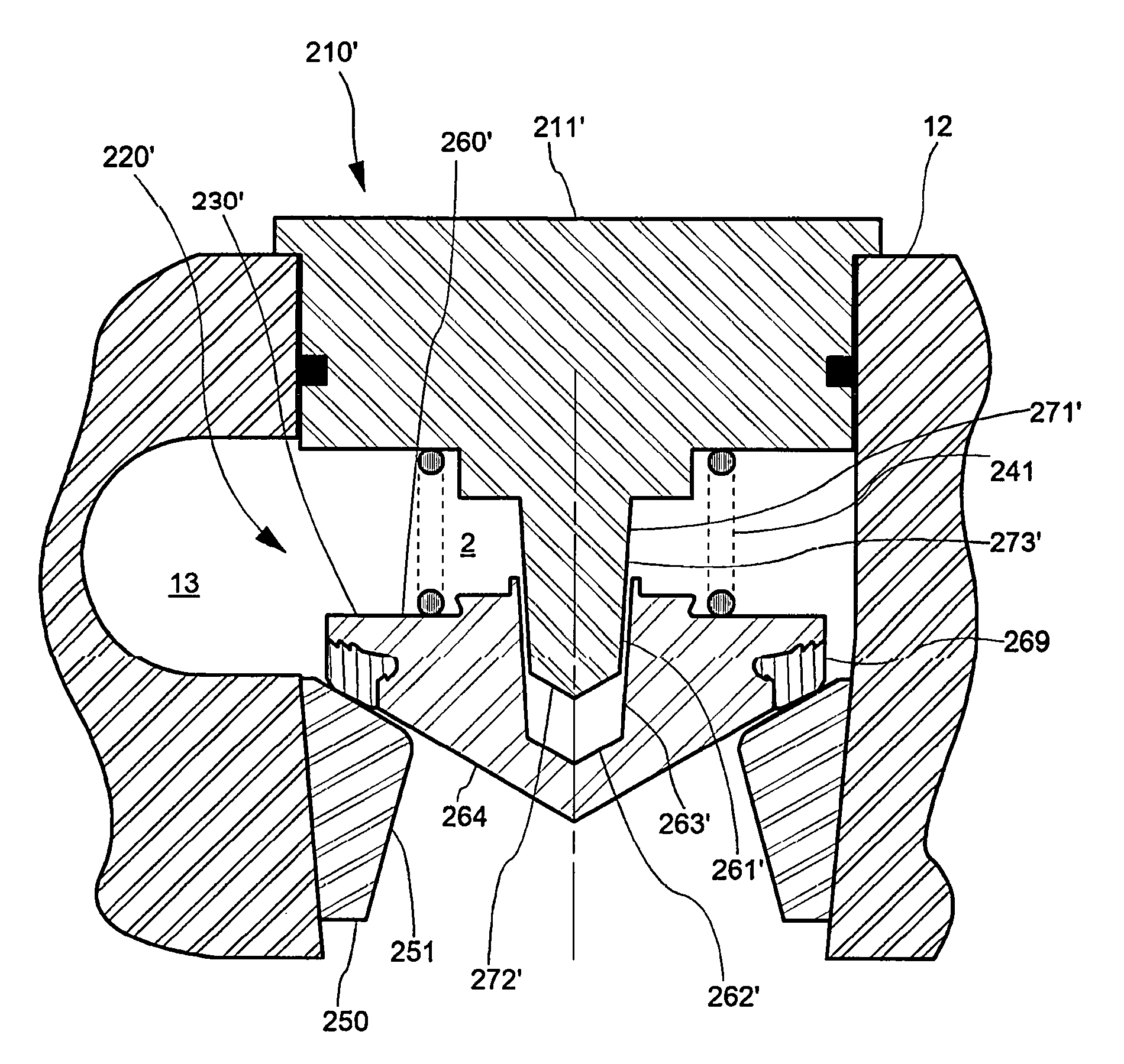
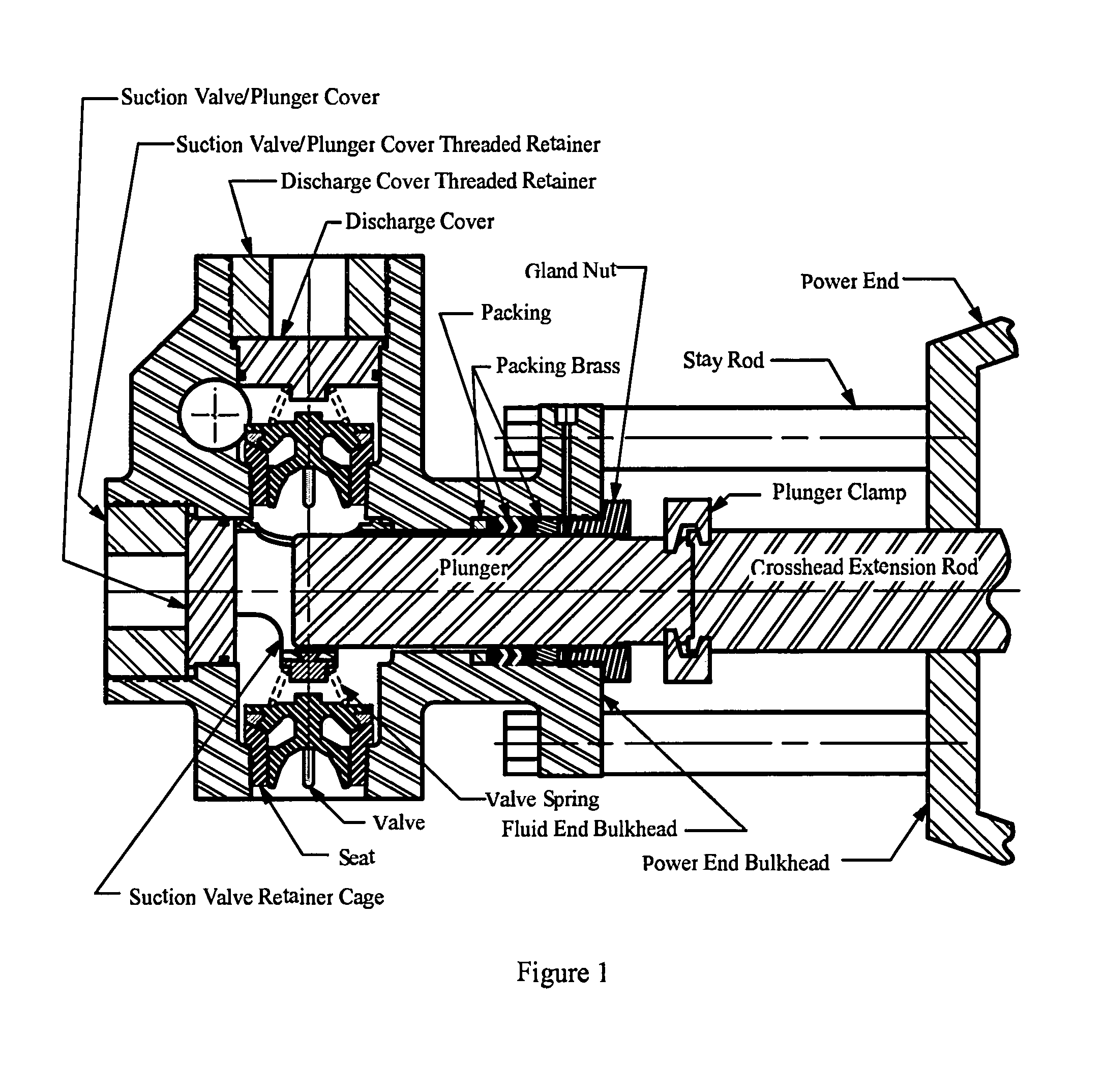
[0068]FIG. 14A schematically illustrates a cross-section of a right-angular plunger pump fluid end housing 12, with a fluid chamber 1, having internally guided suction and discharge valves of the present inventions. Fluid Chamber 1 has discharge fluid chamber 2 and a suction chamber 3, wherein discharge fluid chamber 2 contains a discharge seat 250, discharge valve and seal assembly 230, discharge cover 211, male stem guide 271, and a discharge spring 241. Suction fluid chamber 3 contains a suction seat 350, suction valve and seal assembly 330, suction valve spring retainer 311, suction male stem guide 371, and a suction spring 341. Fluid chamber 1 also contains a plunger 14. Discharge fluid chamber 2 is connected to adjacent discharge fluid chambers by a discharge manifold 13.

[0069]FIG. 14B schematically illustrates an embodiment of the present invention. Discharge valve assembly 210 is positioned in the discharge fluid chamber 2, which is one of multiple chambers inside fluid end ...


PUM


Abstract

A positive displacement pump fluid end with multiple fluid chambers and each fluid chamber comprising a valve body, valve seal, seat, spring, and external guide. External top male stem guide is integral to the fluid end discharge cover or the suction valve spring retainer. Female guide is internal and integral with the valve body. When the valve opens hydrodynamic forces and moments align the valve to prevent rotation. An embodiment features tapered male and female guide members to further assist in correct alignment of the valve with the seat. Various additional embodiments assist in venting any trapped fluids between the male and female portions of the guide.

Description

FIELD OF THE INVENTION[0001]The invention generally concerns high-pressure plunger-type pumps useful, for example, in oil well hydraulic fracturing. More specifically, the invention relates to valves suitable for rapid open-close cycling when pumping abrasive fluids, such as sand slurries at high pressures.BACKGROUND OF THE INVENTION[0002]Engineers typically design high-pressure oil field plunger pumps in two sections; the (proximal) power section and the (distal) fluid section. The power section usually comprises a crankshaft, reduction gears, bearings, connecting rods, crossheads, crosshead extension rods, etc. The power section is commonly referred to as the power end by the users and hereafter in this application. The fluid section is commonly referred to as the fluid end by the users and hereafter in this application. Commonly used fluid sections usually comprise a plunger pump housing having a suction valve in a suction bore, a discharge valve in a discharge bore, an access bo...

Claims


Application Information

Patent Timeline
Patent Type & Authority Patents(United States)
IPC IPC(8): F16K21/04F04B53/10F04B15/02F16K1/36F16K15/06
CPCF16K1/36F16K15/063F16K21/04F04B15/02F04B53/10Y10T137/85978
Inventor BLUME, GEORGE H
Owner ALTIS INVESTMENTS LLC
Why Eureka
Try Eureka