Deep ultraviolet laser generation device and light source device

a laser generation device and laser technology, applied in the direction of optics, instruments, active medium materials, etc., can solve the problems of affecting and affecting the efficiency of the laser. , to achieve the effect of extending the life of the duv laser generation device, preventing damage or degradation of optical elements, and being highly practical

Active Publication Date: 2016-08-30
OXIDE
View PDF8 Cites 1 Cited by
  • Summary
  • Abstract
  • Description
  • Claims
  • Application Information

AI Technical Summary

Benefits of technology

[0018]The present disclosure solves at least one of the problems mentioned above, and, by substantially extending the life of a DUV laser generation device, it contributes to development of a highly practical DUV laser generation device and light source device.
[0019]To solve the problems mentioned above, the present disclosure provides a scheme for generating a DUV light at around 213 nm without producing other DUV light than output one. Since damage or degradation of optical elements is effectively prevented in the nonlinear wavelength conversion element, it is possible to manufacture a DUV laser generation device and light source device with improved reliability.
[0023]As mentioned earlier, the ultraviolet light at a wavelength around 213 nm based on the DUV laser generation device of the present disclosure is produced through SHG of a light source of visible (or blue) light at the wavelength around 426 nm. The blue light at around 426 nm has lower photon energy than that of the fourth harmonic at ˜266 nm of the light source of 1.064 μm due to the longer wavelength and exhibits less absorption in optical materials accordingly. This ensures the present invention to have extremely less probability of causing damage in optical elements. In embodiments provided by the present disclosure, a continuous-wave single frequency blue light source of a wavelength around 426 nm with 3 W-5 W output power is provided, and the blue light at 426 nm is then directly used to generate DUV laser light at a wavelength of 213 nm through the SHG. Therefore, it is possible in accordance with aspects of the present disclosure to operate the generation of DUV light while preventing damage in the optical elements that might be caused by the DUV light, and it is possible to improve reliability of the DUV laser generation device, which results in longer life of the device. Thus, DUV laser generation device and light source device provided in the present disclosure are promising sources in the application field of semiconductor manufacturing process of 14 nm design-rule, which is the state-of-the-art semiconductor nanofabrication process at the time of the present disclosure, and in the application field of wafer and mask inspections for the next generation semiconductor manufacturing processes.
[0025]In accordance with embodiments provided by the present disclosure, it is possible to provide a deep ultraviolet laser at a wavelength that corresponds to a fifth harmonic of the laser light source around 1.064 μm adopting neodymium or ytterbium, which wavelength is demanded in the industry. As a result, the present disclosure provides a continuous-wave deep ultraviolet laser having a short wavelength and high output power capability with high practicability thanks to its high stability and long product life.

Problems solved by technology

Moreover, paths to the wavelength of 213 nm from such lasers are practically limited to fifth harmonic generation from such lasers, that is, a sum frequency mixing process using the fourth harmonic and the fundamental.
In addition to the wavelength selection range and maximum output power capability limitations, the degradation of the wavelength conversion element is also a limiting factor to the output power of the laser source at 213 nm, as mentioned earlier.
This leads to noticeable degradation of the wavelength conversion element itself, which affects reliability of the laser sources of the nonlinear wavelength conversion type.

Method used


Image

  • Deep ultraviolet laser generation device and light source device
  • Deep ultraviolet laser generation device and light source device
  • Deep ultraviolet laser generation device and light source device

Examples


Embodiment Construction

[0035]An embodiment of the deep ultraviolet (DUV) laser generation device of the present disclosure is described below by referring to the drawings. In the following description, common parts or elements are indicated by common reference numerals over the entire drawings unless otherwise noted. In addition, each element in the drawings is not necessarily drawn to scale. In the description of the embodiments provided herein, any light is either laser light or coherent light that has been amplified from laser while keeping its coherence, if not otherwise specified, and a wavelength range of any light is not limited to visible range and may include infrared or ultraviolet range.

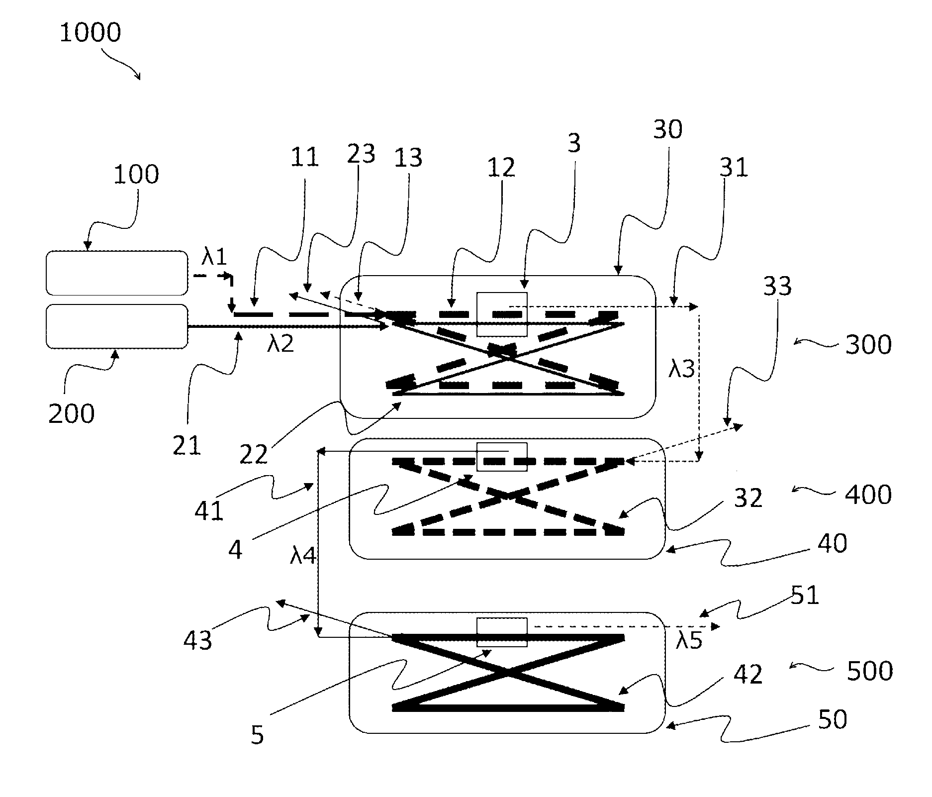
[0036]FIG. 1 shows an example structure of a DUV laser generation device 1000 for generating DUV light using a sum-frequency mixing process and dual-stage second harmonic generation (SHG) processes from beams of light emitted by sources of the first wavelength λ1 and second wavelength λ2. A DUV light 51 at a wav...


PUM

PropertyMeasurementUnit
wavelengthaaaaaaaaaa

Abstract

In one embodiment, the present disclosure provides a deep ultraviolet laser generation device 1000 having a first laser source 100 at a first wavelength between 1.87 μm and 2.1 μm, a second laser source 200 at a second wavelength between 1.53 μm and 1.57 μm, a nonlinear wavelength conversion element 3 for generating near-infrared light 31 at a wavelength between 841 nm and 899 nm through a sum-frequency mixing (SFM) process, a nonlinear wavelength conversion element 4 for generating blue light 41 at a wavelength between 420 nm and 450 nm from the near-infrared light through a second harmonic generation (SHG) process, and a third nonlinear wavelength conversion element 5 for generating deep ultraviolet light 51 at a wavelength between 210 nm and 225 nm from the blue light, through another SHG process. The first laser source may be a thulium-doped laser source or a thulium-doped fiber source, and the second laser source may be a semiconductor laser source, an erbium-doped fiber source, or an erbium / ytterbium-doped fiber source.

Description

BACKGROUND[0001]1. Technical Field[0002]The present disclosure relates to a laser generation device and laser light source device. More specifically, the present disclosure relates to a laser generation device and laser light source device for producing a continuous-wave laser of deep ultraviolet (deep-UV, or DUV) at a wavelength around 213 nm by using nonlinear wavelength conversion techniques.[0003]2. Description of the Related Art[0004]Laser sources using wavelength conversion by nonlinear materials are now widely deployed into industry; however, they still suffer from reliability issues. Limiting factors to the reliability include damage and / or degradation in nonlinear optical crystal elements used for wavelength conversion. The damage / degradation comes from small spot size of the laser light focused onto the crystal; it follows that, even a minor damage / degradation can cause significant decrease in efficiency because the conversion takes place in an optical resonator. When the ...

Claims


Application Information

Patent Timeline
Patent Type & Authority Patents(United States)
IPC IPC(8): H01S3/30H01S3/16H01S3/10H01S3/23G02F1/37H01S3/067H01S3/109
CPCG02F1/3534G02F1/37H01S3/067H01S3/10H01S3/16H01S3/06754H01S3/10092H01S3/109H01S3/1608H01S3/1616H01S3/23G02F2001/3507H01S3/1062H01S3/1671H01S3/0092G02F1/3507
Inventor KANEDA, YUSHI
Owner OXIDE
Why Eureka
Try Eureka