Submersible progressive cavity pump driver

a submersible and progressive technology, applied in the direction of positive displacement liquid engines, liquid fuel engines, borehole/well accessories, etc., can solve the problems of mechanical wear of rods and tubing strings, high service times, and large manpower exposure, so as to reduce the overall size of production tubes, reduce costs, and extend the operational life of string strings

Inactive Publication Date: 2016-09-13
CJS PRODION TECH
View PDF13 Cites 10 Cited by
  • Summary
  • Abstract
  • Description
  • Claims
  • Application Information

AI Technical Summary

Benefits of technology

[0021]The driver and external control lines of the present invention eliminate many limitations associated with the use of rod stings to drive a pump. The entire system is ran concurrently with one coiled tubing unit.
[0022]The driver system relieves issues associated with rod and tubing wear, as it does not have rods, therefore no rod wear. It also does not store torque like a conventional system, as there are no rods to twist up and store energy. The motor is solidly connected to the pump which allows the pump to be turned backwards, which is advantageous for self flushing, and assuring de-torque.
[0023]The driver also alleviates issues with the rods occupying space in the production tubing, as it has no rods. Accordingly we are able to run alternative materials for our production tubing, which combats corrosion and can vastly extend the operational life of the entire string, and allows use of friction reduced products, which allows reduction of the overall size of the production tube, thus reducing cost and allowing for a greater range of activities in the size limited well bores.
[0024]The driver also alleviates issues with spacing out the rotor as the rotor is ran in place inside the stator already at the appropriate setting before placement downhole. As there are no rods again, there is no fear of the rotor shifting it's placement due to stretch, or other forces. The driver does not require a tag bar tool.
[0025]The driver allows for the same type of flush servicing as the prior art, but in a much easier and more reliable fashion. First of all, only the coiled tubing unit (CTU) is required, not a flush-by as well. The CTU runs inside of the production tube very easily as there are no rods, past the motor which is off center to allow this and down to the top of the rotor. The production tube is then circulated over and cleaned out. In order to flush the well, the motor is run in reverse, turning the pump backwards which is possible because we have no rods or tubing to worry about turning off. Once the well is flushed, the system is put on normal pumping operations.

Problems solved by technology

The entire process requires multiple pieces of equipment, service rig, rod rig, co-rod rig, accelerators, tubing x-ray inspectors, etc. which leads to high service times and large man power exposure.
One of the main disadvantages of this system is the mechanical wear that occurs on the rod and tubing string due to the rotation of the rods.
This usually eventually wears holes in the jointed tubing, and weakens the rods.
This leads to rod / tubing failures, which then require servicing.
Additionally, because the rods are rotated from surface, when a pump seizes or fails, the rotary head at surface builds up and stores torque.
This is ran, because when the torque is let off of the rod string the string tends to back turn violently (which besides being a safety concern) can cause the tubing to back off and come apart, thus falling down hole.
This highlights another limitation of this system in that you cannot turn the rotor backwards (which would be advantageous) because the tubing may back off, or any of the rod connections may back off because when rotating backwards, the threads can loosen off.
The rod / tubing combination is also a limitation because the rods are ran inside the production tubing which then takes up space and causes additional restriction of the production area.
The rods also increase the overall surface area, which increases friction loss.
Additionally the friction loss is difficult to combat because of the concentric nature of this design.
Alternative materials (plastics, fiberglass, etc.) that would normally assist in friction reduction cannot be used due to the aggressive nature of the rotation of the steel rods.
It is also difficult to space out the rotor properly.
This action, while fairly reliable, is by no means certain.
This is a major drawback, as these types of wells tend to have a variety of corrosive fluids and gases present.
This very often leads to corrosion issues on the production string and rods, as well as scale build up in the production string and rods.
Due to the rotary action of the rods, lined jointed tubing cannot be used as the rods would beat it up, and destroy it with their rotary motion and wear.
Often with heavy oil wells, the pump sands off and this requires servicing.
This operation also requires multiple service units, and often, because of the unpredictability of the rods inside of the production tubing, the coil unit may not be able to get entirely down, or worse, could become stuck, or lodged around the rods.
Unfortunately if the programming reads it is torquing up, all it can do is shut it down.
The system then sits static until equipment can be mobilized, (which can be days) and while the well sits idle, the solids that are suspended in the production column begin to settle back down on top of the rotor, which typically means that when the equipment arrives, the flush-by cannot pull the rotor out of the stator to perform the flush.
If the coil unit is unsuccessful, a complete service may be required with a service rig which includes pulling everything out of the hole, including the tubing.
As mentioned above, the connections that are inherent with this type of system are prone to backing off if the rods / pump are turned backwards.
Additionally, as the rods torque up, they store energy, so that once the system goes down on high torque, the rods have a lot of stored energy.
When this occurs, there is a risk of the aforementioned back off of the tubing.
If that occurs, the tubing / rods can fall down the hole, causing additional problems.
Because this tool is in contact with the casing, it is difficult, or impossible to get past it with anything to clean out the cellar / sump of the well.

Method used


Image

  • Submersible progressive cavity pump driver
  • Submersible progressive cavity pump driver
  • Submersible progressive cavity pump driver

Examples


first embodiment

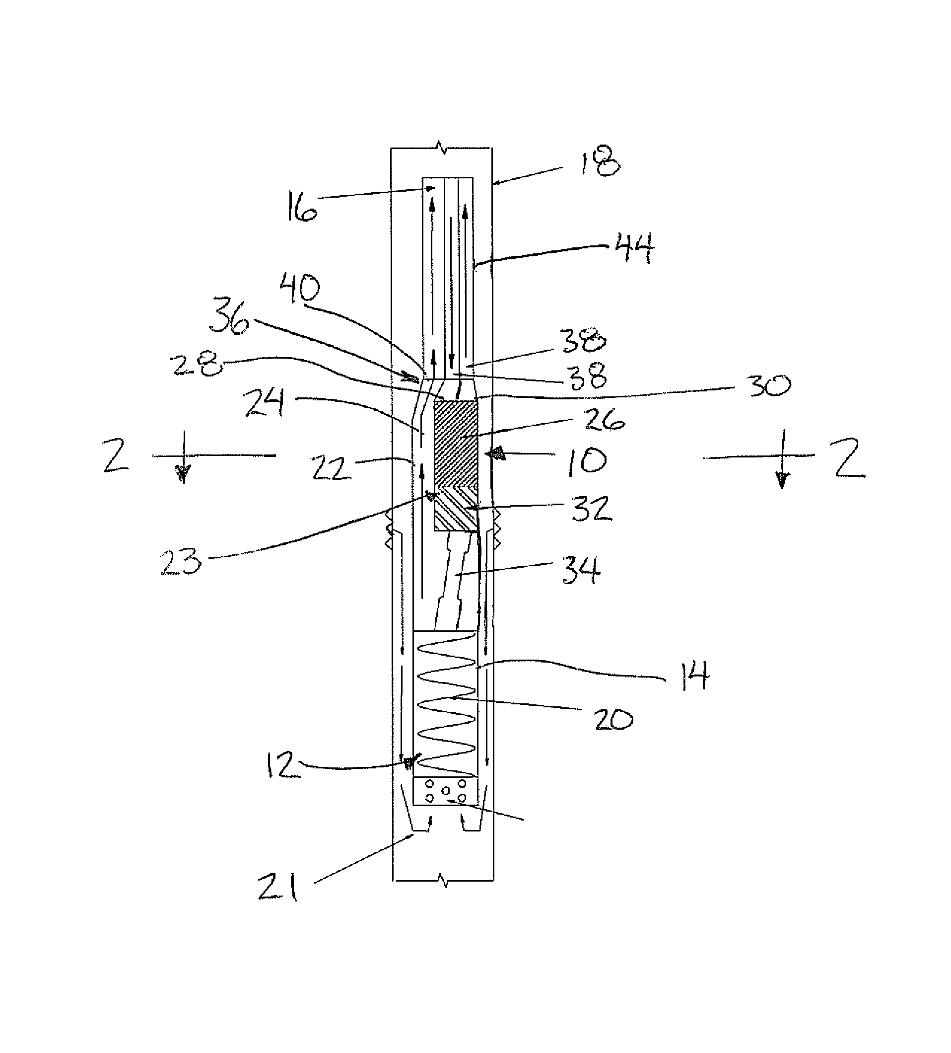
[0085]Turning now more particularly to the production housing 22 of FIGS. 1 and 2, the motor connection 23 in this instance comprises an integral connection between the production housing and the motor chamber locating the drive motor 26, and bearing box 32 therein. The production passage of the production housing is supported to extend alongside the drive motor such that the production outlet at the top end of the housing and the input to the drive motor are arranged for direct connection to the connector 36 which connects to the production tubing and the control lines thereabove. The drive motor is supported in this instance by the motor connection of the production housing such that the output axis of the motor is offset in a radial direction from the stator of the progressive cavity pump therebelow and the production tubing connected to the production outlet of the production housing thereabove.

[0086]Turning now more particularly to the second embodiment of the production housin...

second embodiment

[0088]In the second embodiment, the production outlet of the production housing 22 communicates in series with an auxiliary production tube 100 which extends alongside the drive motor between the production housing and the connector 36. A top end of the auxiliary production tube 100 may be offset from the bottom end such that the top end can optionally be located coaxially with the motor output at a location above the motor when the bottom end is coaxial with the production outlet of the production housing 22.

[0089]As shown in FIG. 5, when the second embodiment of the production housing 22 is used with the production tubing of FIG. 4, the production port in the connector may be arranged to connect between the production tubing thereabove and the auxiliary production tube 100 therebelow such that the motor is suspended in line below the production tubing with an output of the motor and the pump stator therebelow being substantially coaxial with a central longitudinal axis of the prod...


PUM


Abstract

In a rotary pump having a rotor and a stator in communication with hydrocarbon production tubing, a submersible pump driver assembly includes a drive motor having an output connected by a drive link to the rotor of the pump. A production housing of the drive assembly includes a production passage receiving the drive link in which the output axis of the drive motor is radially offset from the passage. A control line for providing a drive input to the motor is thus suited to extend alongside the production tubing. The driver assembly thus allows for flushing with only a coiled tubing unit as the coiled tubing can be readily inserted past the offset motor and the motor can be optionally run in reverse to improve flushing.

Description

[0001]This application claims the benefit under 35 U.S.C. 119(e) of U.S. provisional application Ser. No. 61 / 407,750, filed Oct. 28, 2010.FIELD OF THE INVENTION[0002]The present invention relates to a hydraulic submersible driver for a rotary pump, for example a progressive cavity pump, in which the driver is offset in relation to the production tubing; and more particularly, the present invention relates to a method of operating the rotary pump using the driver so that the pump can be operated in reverse for flushing operations. The present invention further relates to a suitable connector for connection between the driver and the production tubing so that control lines of the driver can be located alongside and externally of the production tubing.BACKGROUND[0003]Currently, and in the past, progressive cavity pumps have been ran in two pieces. First, the stator portion is ran in on standard jointed tubing. Then, the rotor portion is ran in on either jointed rods, or co-rod and stab...

Claims


Application Information

Patent Timeline
Patent Type & Authority Patents(United States)
IPC IPC(8): E21B17/02F04C15/00E21B21/00F04B47/06E21B43/12F04C13/00F04C2/107
CPCE21B43/129E21B17/02E21B21/00E21B43/128F04B47/06F04C2/1071F04C13/008F04C15/0061
Inventor MORRIS, COLLIN RICKEYRECK, JOSEPH HENRYBUDENSKI, ADAM
Owner CJS PRODION TECH
Why Eureka
Try Eureka