Drill bit and cylinder body device, assemblies, systems and methods

a technology of drilling cylinders and cylinder bodies, which is applied in the direction of drilling pipes, borehole/well accessories, surveys, etc., can solve the problems of increasing the degree of drilling complexity, requiring significant manpower and equipment, and rotating equipment is particularly prone to maintenance,

Active Publication Date: 2016-10-11
ZURN WILLIAM HARRISON
View PDF59 Cites 27 Cited by
  • Summary
  • Abstract
  • Description
  • Claims
  • Application Information

AI Technical Summary

Problems solved by technology

Drilling an oil field well for hydrocarbons requires significant expenditures of manpower and equipment.
Rotating equipment is particularly prone to maintenance as the drilling environment produces abrasive cuttings detrimental to the longevity of rotating seals, bearings, packing glands and drill bits.
In drilling well bores, formation rigidity and an equivalent degree of drilling complexity may increase exponentially as a function of escalating depth.
A high percentage of the costs to drill a well bore are derived from interdependent operations that are time sensitive, i.e., the longer it takes to access the formation being drilled, the higher the expense.
An important aspect affecting the cost of drilling a well bore is the rate at which the formation can be accessed by the drill bit, which typically decreases with harder and tougher formation materials and formation depth.
As a result, drilling costs typically tend to increase significantly, with distance downward or horizontal into a formation.
There was sufficient illustration that the use of entrained abrasives in conjunction with high drilling fluid pressures produced accelerated erosion of surface equipment and a lack of ability to manage drilling mud density, among other issues.
These issues incur cost and time delays objectionable to drilling operations in the oil exploration market.
These devices are written off in the event that this section of the drill string becomes trapped downhole, and as a result discarded if efforts to liberate the device are unproductive.
The obstacles of pumping and transporting ultra-high-pressure fluid from surface pumping equipment to the drill bit proved both operationally and economically unfeasible.

Method used


Image

  • Drill bit and cylinder body device, assemblies, systems and methods
  • Drill bit and cylinder body device, assemblies, systems and methods
  • Drill bit and cylinder body device, assemblies, systems and methods

Examples


Embodiment Construction

[0073]Before the present systems and methods are described, it is to be understood that this invention is not limited to particular embodiments described, as such may, of course, vary. It is also to be understood that the terminology used herein is for the purpose of describing particular embodiments only, and is not intended to be limiting, since the scope of the present invention will be limited only by the appended claims.

[0074]Where a range of values is provided, it is understood that each intervening value, to the tenth of the unit of the lower limit unless the context clearly dictates otherwise, between the upper and lower limits of that range is also specifically disclosed. Each smaller range between any stated value or intervening value in a stated range and any other stated or intervening value in that stated range is encompassed within the invention. The upper and lower limits of these smaller ranges may independently be included or excluded in the range, and each range wh...


PUM


Abstract

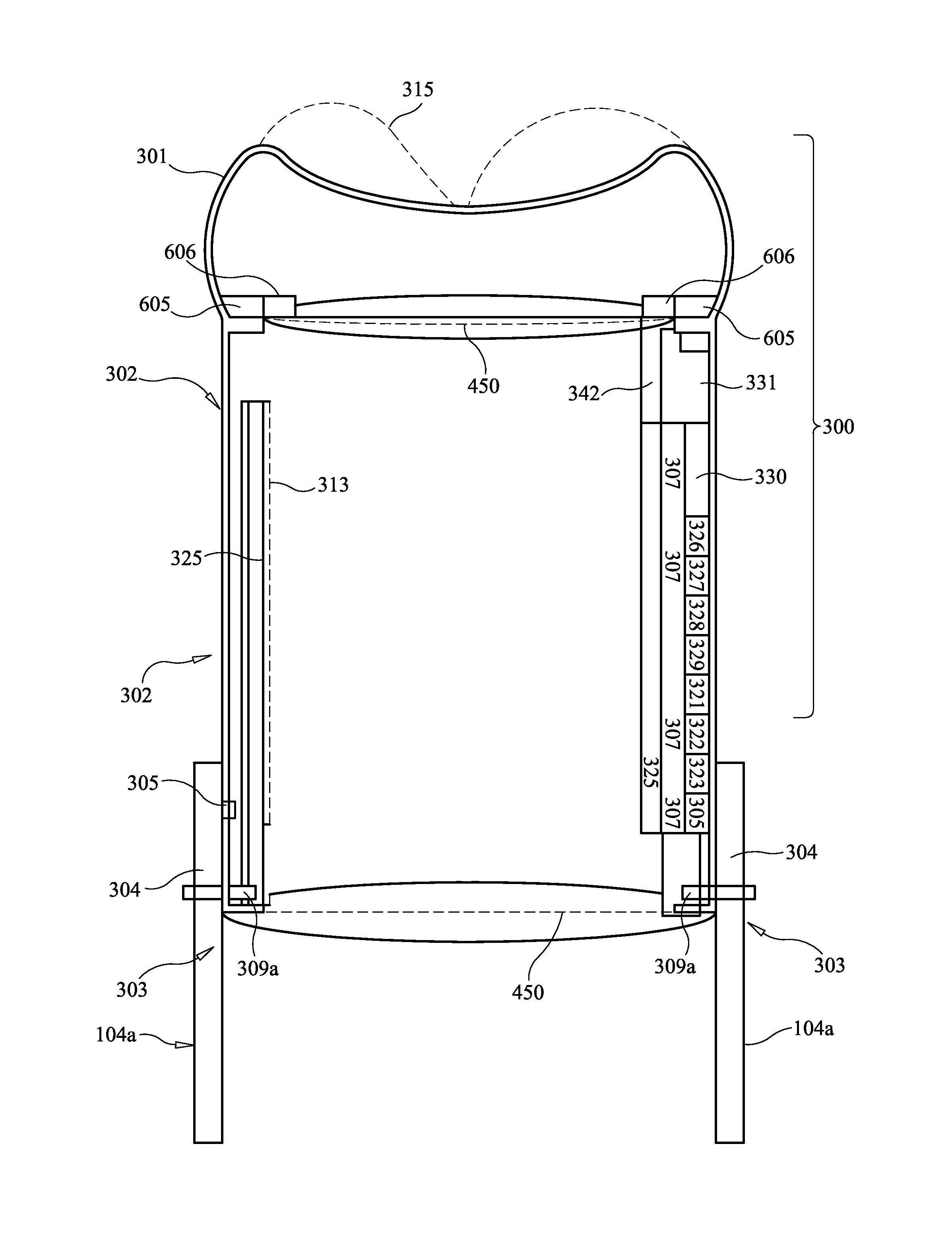
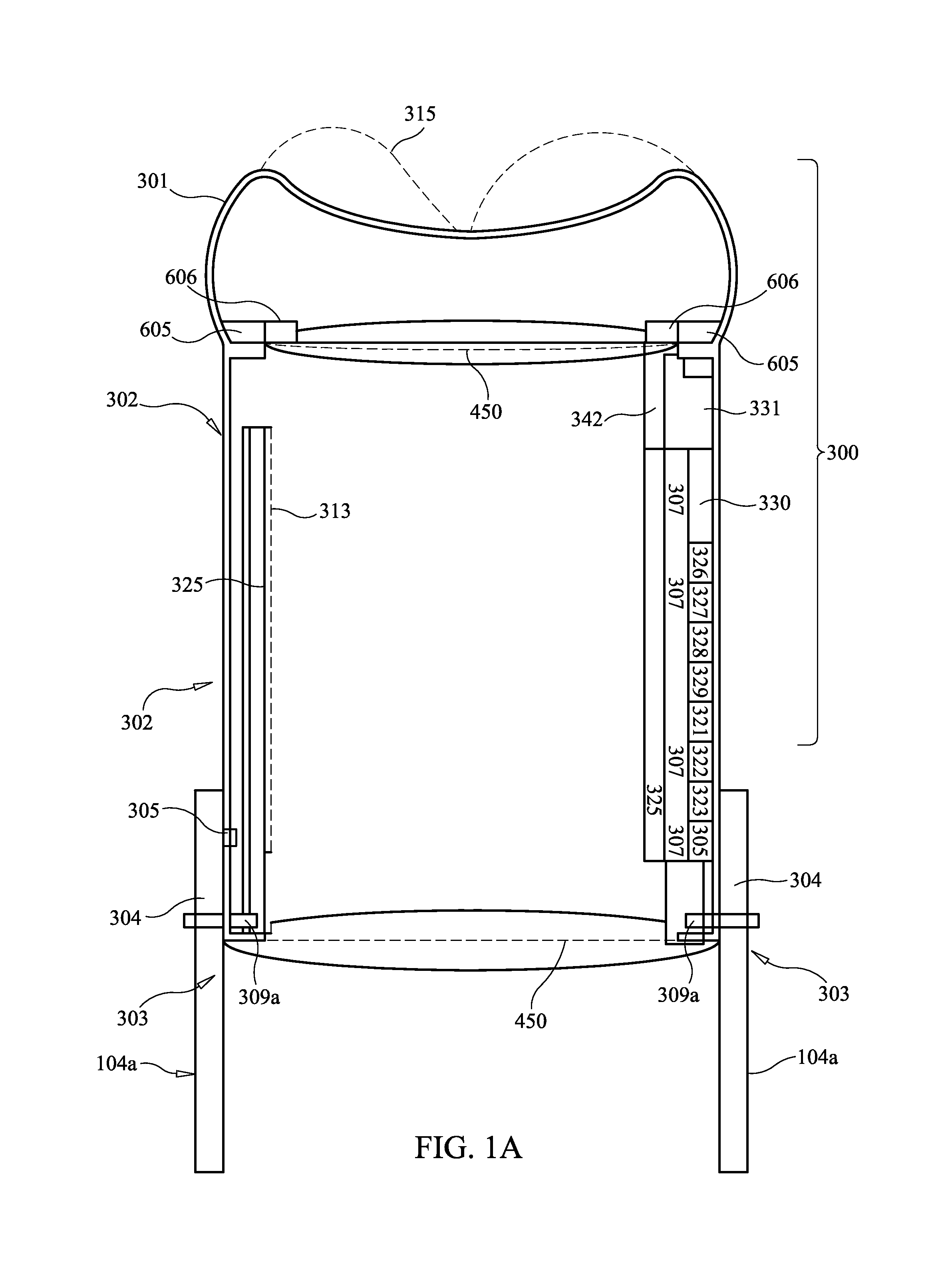
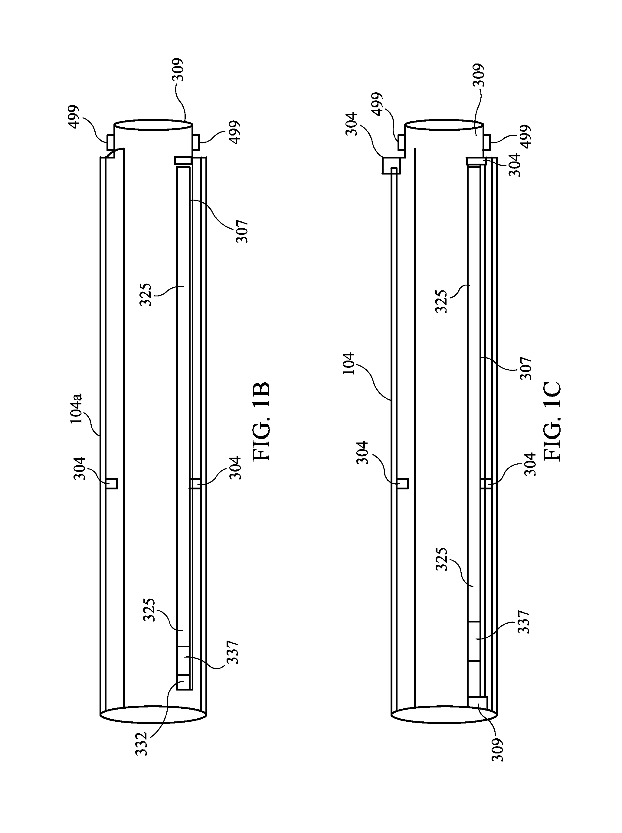
A drilling system includes a cylinder body and drill bit assembly. The drill bit includes a plurality of drill bit blades, each having at least one drill bit element. A cylinder body is connected to the drill bit. A plurality of transmitters are mounted on each drill bit element and transmit data characterizing a degree of wear of the drill bit to a data transmitter and receiver of the cylinder body that is in communication with the plurality of transmitters.

Description

FIELD OF THE INVENTION[0001]The present invention relates to drill bit and cylinder devices used for drilling into rock, soil, and various types of muck. The present invention relates to coupling and decoupling drill bits to cylinder housings for use with horizontal or vertical directional drilling operations.BACKGROUND OF THE INVENTION[0002]Drilling an oil field well for hydrocarbons requires significant expenditures of manpower and equipment. Constant advances are being sought to reduce any downtime of equipment and expedite any repairs that become necessary. Rotating equipment is particularly prone to maintenance as the drilling environment produces abrasive cuttings detrimental to the longevity of rotating seals, bearings, packing glands and drill bits.[0003]A well bore is any hole drilled for the purpose of exploration or extraction of natural resources such as water, gas or oil where a well may be produced and a resource extracted for a protracted period.[0004]The method of dr...

Claims


Application Information

Patent Timeline
Patent Type & Authority Patents(United States)
IPC IPC(8): E21B10/00E21B47/12E21B4/00E21B3/00E21B12/02
CPCE21B3/00E21B4/00E21B47/122E21B12/02E21B47/01E21B47/12E21B7/046E21B10/64E21B17/028E21B17/046E21B47/013
Inventor ZURN, WILLIAM HARRISON
Owner ZURN WILLIAM HARRISON
Why Eureka
Try Eureka