
Wirelessly powered medical devices and instruments

a medical device and a technology of medical devices, applied in the field of wireless medical devices, can solve the problems of large amount of cables required for operation, heavy endoscope top, and difficult maneuverability for users,

Active Publication Date: 2016-12-27
KARL STORZ IMAGING INC
View PDF55 Cites 186 Cited by
  • Summary
  • Abstract
  • Description
  • Claims
  • Application Information

AI Technical Summary

Benefits of technology

This patent is about a new system and method for medical devices that solves problems with traditional wired and battery-powered devices. It also reduces the weight of the instrument, eliminates cables, and provides a reliable and cost-effective wireless power transmission system. The technical effects of this patent are improved efficiency, reliability, and reduced weight and cost of medical instruments.

Problems solved by technology

However, one of the major drawbacks of such instruments is the relatively large amount of cables required for operation.
These lines are cumbersome and may even present operational difficulties for the user.
For example, these cables can get in the way of other surgical instruments and also make the endoscope top heavy and difficult to maneuver.
Additionally, surgeons often complain of fatigue because they are constantly working against the weight of the cables attached to their instruments.
Still another problem that cables present is that they can compromise the procedure if mismanaged as contact with the cables, by another individual or with an object, may suddenly cause tugging on an instrument and / or accidentally cause the instrument to be thrust into or impinge upon delicate tissue.
In fact, this problem is so prevalent that many surgeons wrap the cables around their wrists several times to prevent cable forces from transferring directly to their instruments.
In an attempt to address some of the problems associated with “wired” devices, a number of systems have sought to provide “wireless” systems with limited success.
First, battery systems continue to be inherently large, heavy and costly. As was previously stated, physicians that have to manipulate a relatively heavy device or fight against relatively heavy cables, suffer from fatigue, especially in relatively complicated and long surgical procedures.
Another problem with battery-powered systems is that they may not be recharged or they may only be partially recharged, thus causing them to shut down or at the very least, causing the device to function at a non-optimal level (i.e. low voltage level) for a portion of the procedure.
While procedures may be put into place to limit mistakes in the recharging process, human-error will result in some devices not being charged or not being fully recharged.
Still another problem with battery-powered systems is that batteries inherently deteriorate over time.
However, as the battery is used and recharged again and again, that power output slowly decreases until the battery can no longer maintain sufficient charge to operate the medical device for the length of the procedure.
Regular replacement of batteries can limit this problem, however, this greatly increases the cost associated with using wireless devices.
Battery testing can also limit this problem, but this takes time and involves human error if the individual forgets, makes a mistake in testing or misreads the results.
Therefore, the system taught in Yoshida could not be used for an active medical procedure as the power transmitting coil would not regularly be aligned with the receiving coil.
It would be virtually impossible for the surgeon to perform the procedure if the surgeon had to maintain the tool in alignment with the power transmitter as the surgeon needs to freely move the tool without regard to external issues.
In any event, the capsule system is certainly not designed for manipulation by the physician (i.e. it is designed to be ingested by the patient).
Another limitation of the system taught in Yoshida, is that it is not provided to transmit a video stream of information that requires 30-60 frames of information per second.
24-25) In fact, in view of the limited amount of power that can be transmitted to the capsule, it is questionable whether the video could provide a video stream of the area it is slowly passing through.
Additionally, the system taught in Yoshida does not provide for the constant light output needed for continual illumination for video transmission.

Method used


Image

  • Wirelessly powered medical devices and instruments
  • Wirelessly powered medical devices and instruments
  • Wirelessly powered medical devices and instruments

Examples


Embodiment Construction

[0041]Referring now to the drawings, wherein like reference numerals designate corresponding structure throughout the views.

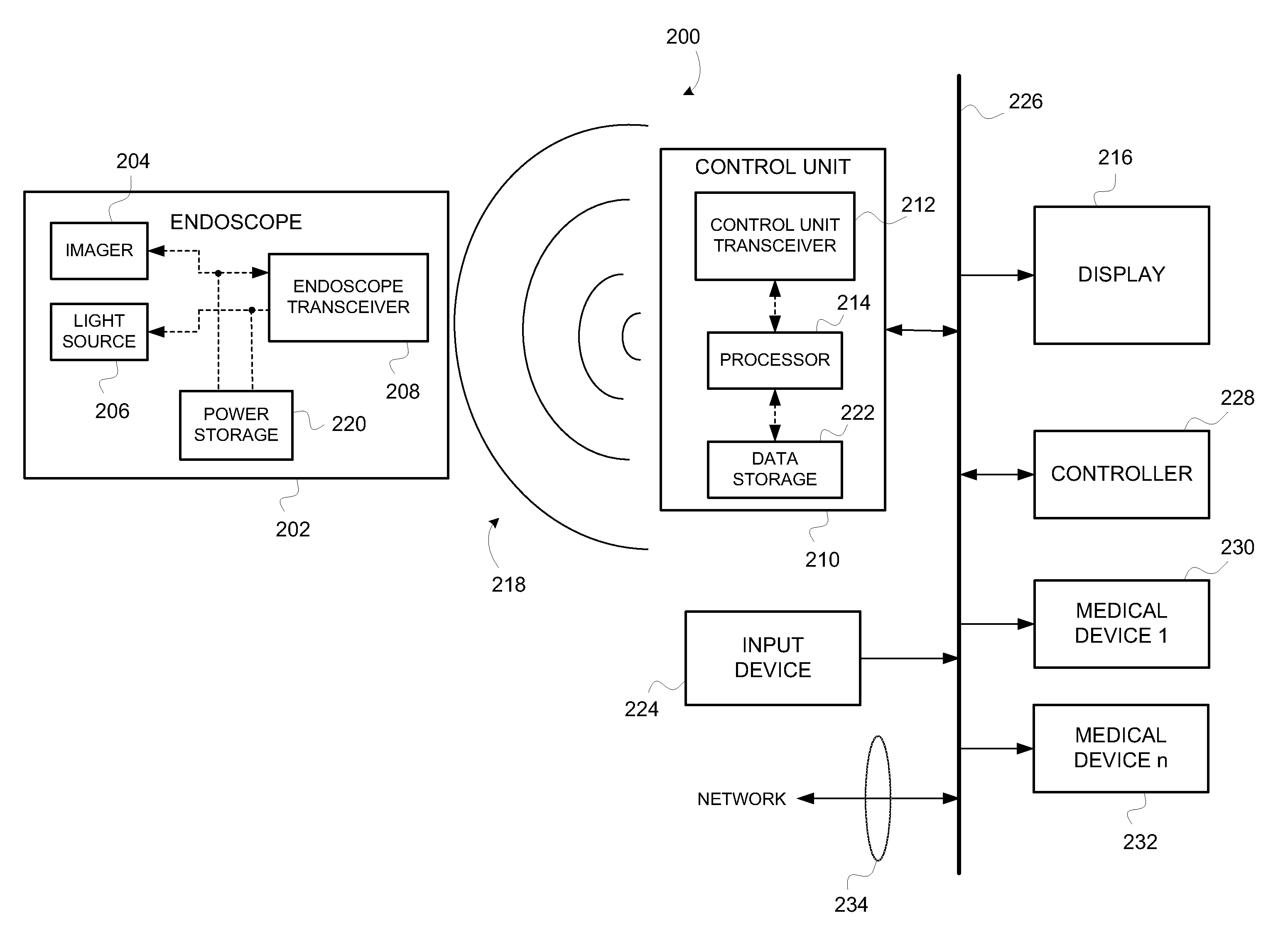
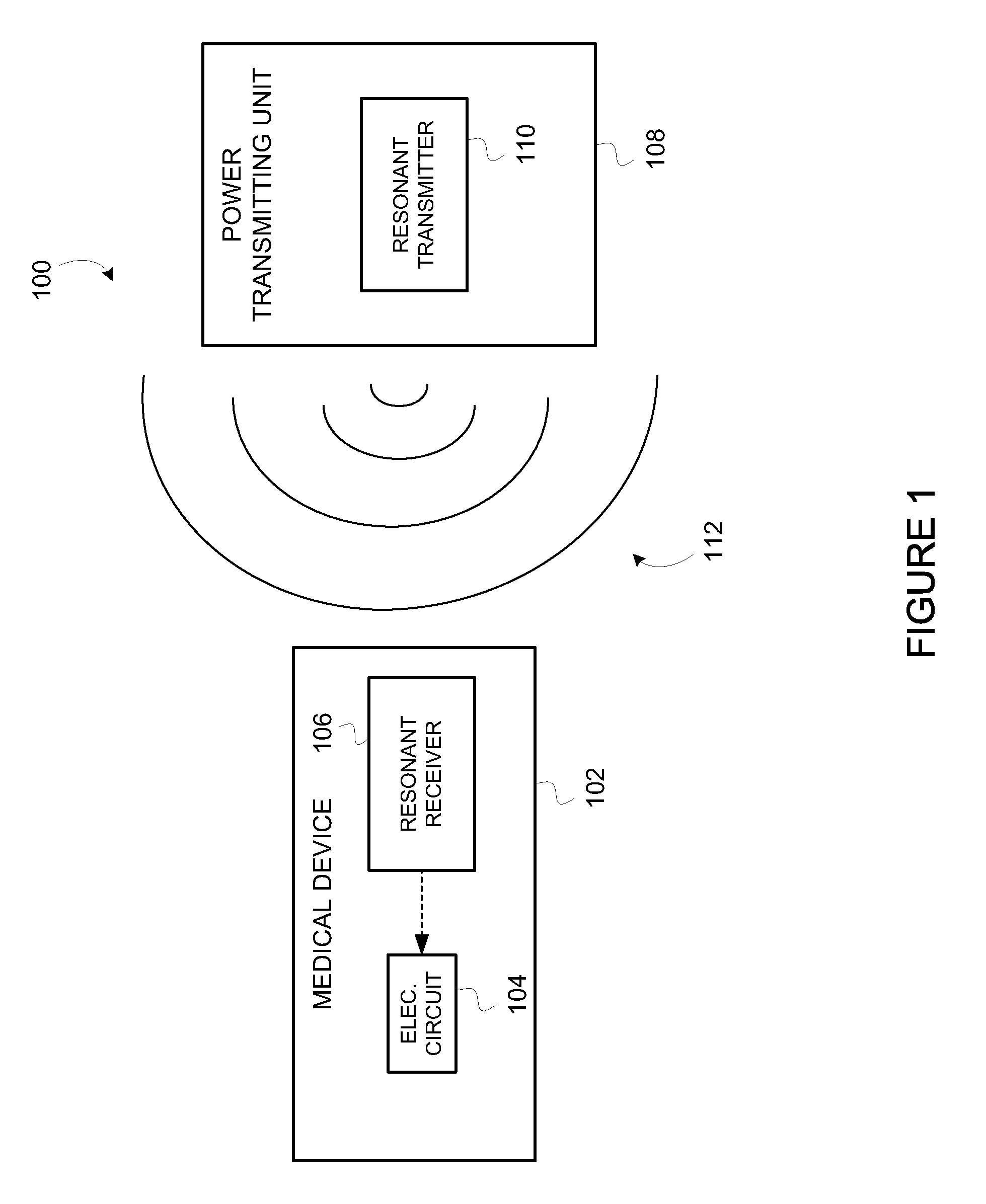
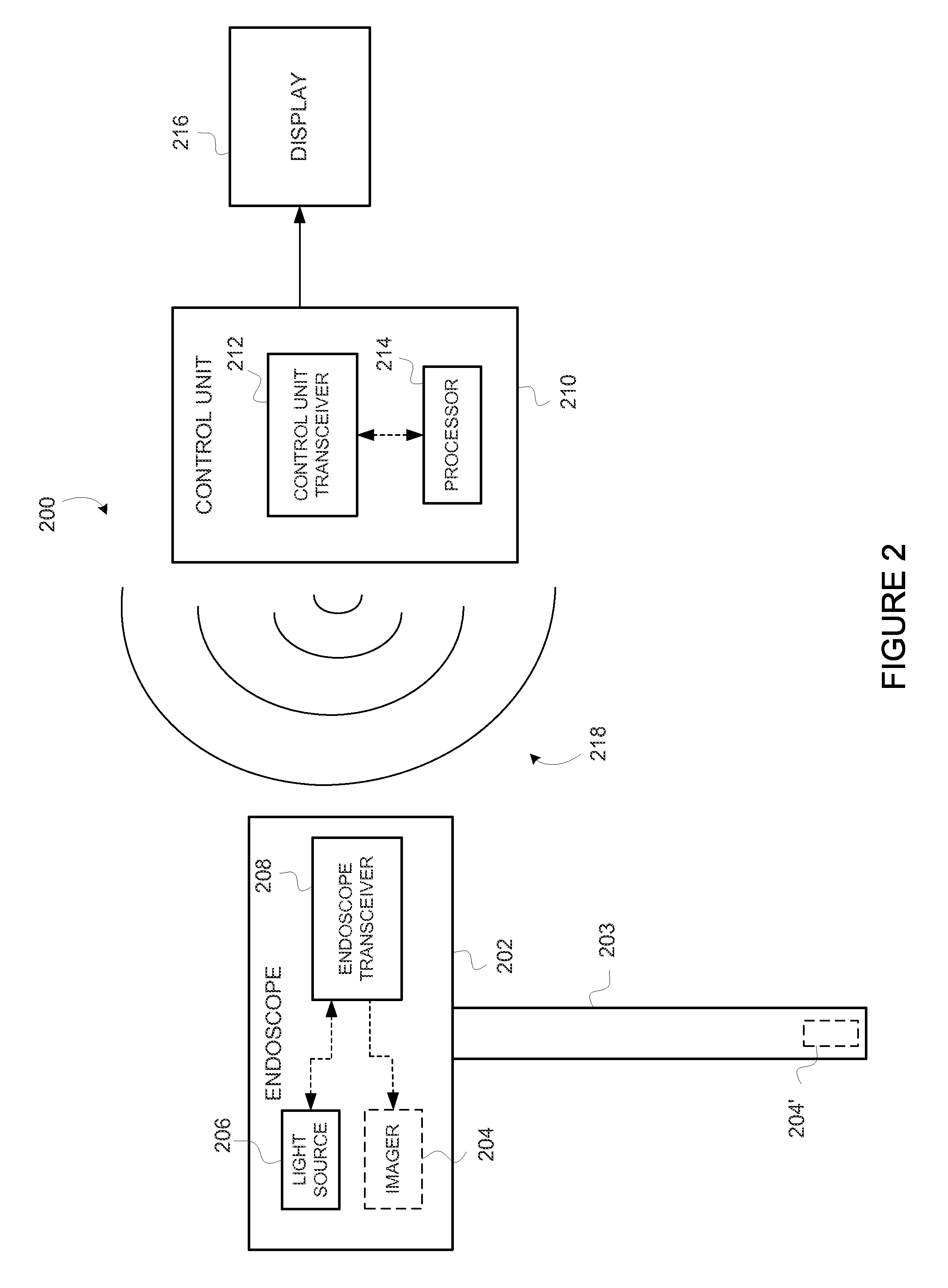
[0042]FIG. 1 generally depicts system 100 for providing electrical power to a medical device 102. It is contemplated that medical device 102 could comprise virtually any type of powered medical device, including but not limited to, a cutting / cauterizing tool, an irrigation / aspiration tool, a visualization tool, a recording and / or printing device and the like. Medical device 102 is provided with electronic circuit 104 and resonant receiver 106. Electronic circuit 104 may comprise any electronic / electrical circuit(s) used to operate medical device 102. Electronic circuit 104 is electrically coupled to resonant receiver 106.

[0043]Also provided in FIG. 1 is power transmitting unit 108 that includes resonant transmitter 110. It is contemplated that resonant transmitter 110 generates a resonant magnetic field 112 (depicted by the concentric lines) that transmits from...


PUM


Abstract

A medical device that is wirelessly powered by a resonant magnetic field, the device automatically coupling to a power transmitter in a control unit when brought within a threshold radius. In one embodiment, the control unit automatically identifies the medical device and automatically adjusts its settings to control the medical device.

Description

CROSS-REFERENCE TO RELATED APPLICATIONS[0001]This application claims the benefit of the filing date of U.S. Provisional Patent Application Ser. No. 61 / 047,967 filed Apr. 25, 2008.FIELD OF THE INVENTION[0002]The invention relates to a wireless medical instrument and more specifically to a medical video instrument that wirelessly receives electrical power for operation of the video instrument.BACKGROUND OF THE INVENTION[0003]Powered medical devices and / or instruments have been in use for many years. However, one of the major drawbacks of such instruments is the relatively large amount of cables required for operation. For example, cutting devices require the use of a power cable to provide electrical power for the medical instrument. Likewise, video endoscopes have traditionally required the use of a power cable and a data transmission line as well as a fiber optic cable for transmission of illuminating light.[0004]These lines are cumbersome and may even present operational difficulti...

Claims


Application Information

Patent Timeline
Patent Type & Authority Patents(United States)
IPC IPC(8): A61B1/04A61B1/00
CPCA61B1/042A61B1/00029A61B1/041A61B1/00016A61B2560/0214
Inventor HOEG, HANS DAVIDANKNER, CHARLES E.
Owner KARL STORZ IMAGING INC
Learn More