

Ferrite magnet with salt and manufacturing method of the same
a technology of ferrite magnets and salts, which is applied in the field of ferrite magnets, can solve the problems of difficult to suppress the growth of ferrite magnetic particles, increase the cost of sintering process, increase the cost of process and other issues, and achieve the effect of preventing cohesion between particles, facilitating nano-sized, and high crystallinity
- Summary
- Abstract
- Description
- Claims
- Application Information
AI Technical Summary
Benefits of technology
Problems solved by technology
Method used
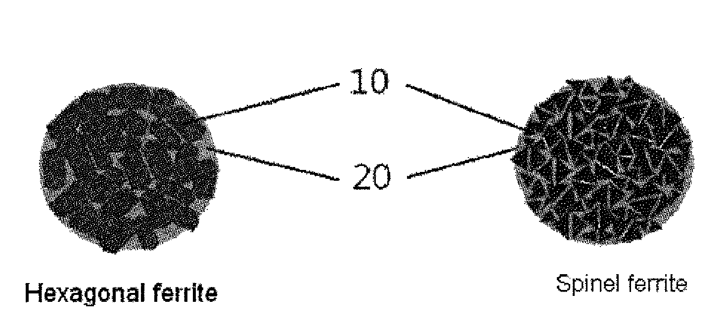
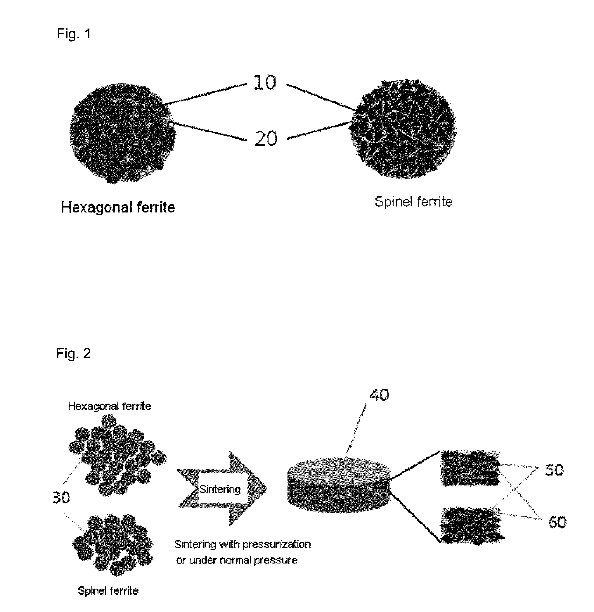
Image

Examples
example 1
[0127]Ba(NO3)2 and Fe(NO3)3.9H2O were used for a source material of barium ferrite. A mixture in which Ba(NO3)2 and Fe(NO3)3.9H2O are mixed in a molar ratio of 1:12 was used for the source material of barium ferrite. Specifically, Ba(NO3)2 and Fe(NO3)3.9H2O were added to deionized water and stirred for about an hour to prepare a source material of barium ferrite comprised of Ba(NO3)2 with a molar concentration of 0.05M and Fe(NO3)3.9H2O with a molar concentration of 0.6M.
[0128]Sodium chloride (NaCl) was added to the source material of barium ferrite to prepare a starting material. The sodium chloride was weighed to have a weight ratio of 19% with respect to ferrite magnetic powder with salt (19 weight % with respect to 100 weight % of ferrite magnetic powder with salt) and added.
[0129]The starting material was sprayed to form liquid droplets and allowed to pass through a reaction chamber heated at an inlet temperature of about 400° C., and an outlet temperature of about 850° C. alon...
example 2
[0134]A starting material was prepared using a source material of barium ferrite and sodium chloride similarly to the Example 1, but sodium chloride was weighed to have a weight ratio of 31% with respect to ferrite magnetic powder with salt (31 weight % with respect to 100 weight % of ferrite magnetic powder with salt) and added.
[0135]The starting material was sprayed to form liquid droplets and allowed to pass through a reaction chamber heated at an inlet temperature of about 400° C., and an outlet temperature of about 850° C. along with a carrier gas (O2) similarly to the Example 1, thereby synthesizing barium ferrite magnetic powder with salt.
example 3
[0136]A starting material was prepared using a source material of barium ferrite and sodium chloride similarly to the Example 1, but sodium chloride was weighed to have a weight ratio of 53% with respect to ferrite magnetic powder with salt (53 weight % with respect to 100 weight % of ferrite magnetic powder with salt) and added.
[0137]The starting material was sprayed to form liquid droplets and allowed to pass through a reaction chamber heated at an inlet temperature of about 400° C., and an outlet temperature of about 850° C. along with a carrier gas (O2) similarly to the Example 1, thereby synthesizing barium ferrite magnetic powder with salt.
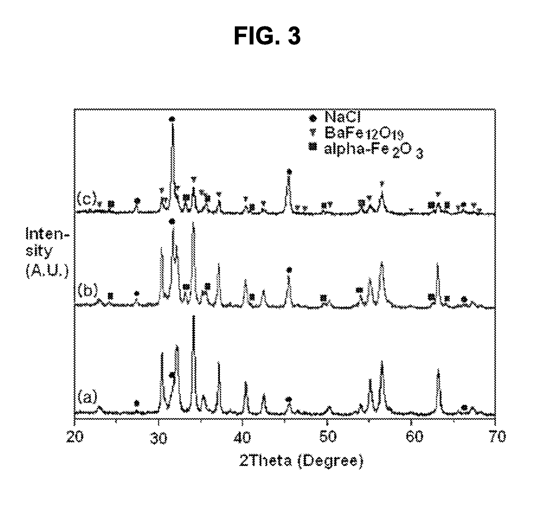
[0138]FIG. 3 is a graph illustrating an X-ray diffraction (XRD) pattern of barium ferrite magnetic powder with sodium chloride synthesized according to Examples 1 through 3. FIG. 3A illustrates an X-ray diffraction (XRD) pattern of barium ferrite magnetic powder with sodium chloride synthesized according to Example 1, and FIG. 3B illustrates...
PUM
| Property | Measurement | Unit |
|---|---|---|
| diameter | aaaaa | aaaaa |
| diameter | aaaaa | aaaaa |
| diameter | aaaaa | aaaaa |
Abstract
Description
Claims
Application Information