Lithium secondary cell array

a secondary cell array and lithium technology, applied in the manufacture of cell components, final product manufacturing, electrochemical generators, etc., can solve the problems of reducing current carrying capacity, complicated technological steps, and power limitation during both charging, and achieves improved wound lithium cell design, low electrical resistance, and simple winding design

Active Publication Date: 2017-05-02
EBERT KLAUS +1
View PDF20 Cites 1 Cited by
  • Summary
  • Abstract
  • Description
  • Claims
  • Application Information

AI Technical Summary

Benefits of technology

[0015]From the foregoing, the object of the invention is to provide a more sophisticated lithium secondary cell array of a cylindrical design which has a winding mandrel and a winding package, the latter comprising foil-like coated strips and contacting strips that form the electrical cell structure of anode, cathode and separator. The lithium secondary cell array to be specified should be of a high current design, whereby a coupling of several cells is to be realised via a corresponding series circuit. At the same time, there should be a possibility of intensively cooling the corresponding cells by simple means so that charging process can be shortened.
[0022]A cell cooling liquid can be easily fed to the lithium secondary cell array via the quasi mechanical series connection of the through-channel and through-passage. Heat generated by the winding core can thus be dissipated to achieve effective cooling.
[0026]In one alternative a clamping ring acts as a force-fit connecting means that is slid over the outer pole cap. The clamping ring can be fixed by a locking device, in particular a circlip. In the case of the embodiment of the force-fit connecting means as a clamping ring, the outer pole cap has a slightly conical design in the area of its chuck-like bulge. Holes for countersunk screws in the first variant of radially arranged force-fit connecting means in the outer pole cap and in the winding as well as corresponding threaded holes in the inner pole cap are not needed. The pressure exerted by the clamping ring ensures adequate contacting and a negligible internal resistance.
[0032]Slot-shaped recesses in the edge area of the foils strip and the conductive insert strips mean that it is possible to supply electrolyte fluid or recirculated electrolyte, whereby the slot-shaped recesses are designed such that these also lie on top of each other in the finished winding.
[0034]Summing up at this point, the invention represents an improved design of wound lithium cells, whereby the pole caps according to the invention presented here are a great improvement over the prior art. The cells designed in this way are particularly capable of high current, whereby the coupling of several cells is possible via a simple connector arrangement, which itself does not take up any great additional volume. Similarly, a heating of the individual and cooling of the series-connected cells is also possible by simple means via a non-conductive fluid through the pole caps. Using an aqueous electrolyte means that it can be replaced without having to dismantle the cells, thus prolonging their useful life. At the end of their operational service life the cells can be easily dismantled to allow an uncomplicated recycling of the respective raw materials.
[0043]The fuse element according to the invention accordingly enables a non-corrosive connection of the axial connecting terminals of two lithium cells connected in series. The release current can be adjusted very finely by the number of locking pins used and by the choice of individual locking pins. This continues to guarantee a constant core cooling of the connected lithium cells. The size and shape of the fuse element can be individually adapted to the cells to be connected. A hexagonal shape, for example, can simplify assembly. A triggered fuse element can be reused by inserting new locking pins. If the diameter of the disks chosen is larger than the diameter of the cells to be connected, the locking pins can be exchanged without having to dismantle the fuse element. The direct installation of the fuse element directly between the cells to be connected does way with the considerable amount of wiring work that is needed on account of the wire cross-sections compared to external fuses. This also leads to fewer contact parts that could cause unnecessary contact resistances. Furthermore, little space is needed. In this way it is possible to fuse individual cells within a continuous array.

Problems solved by technology

In this case, either a plurality of such strips has to be handled, which can lead to mechanical problems such as compression or material breaks, or there is a limitation to a few strips which are led out from the foil winding, but which reduces the current carrying capacity.
However, the electrode contact pins used for contacting, which ensure the desired contacting at certain intervals within the winding, only allow the use of a small part of the material cross-section for the actual current transport.
This means that the power is limited during both charging and discharging of a corresponding lithium secondary cell.
The contacting of the washer with the foil winding is effected through welding, which is a very complicated technological step.

Method used


Image

  • Lithium secondary cell array
  • Lithium secondary cell array
  • Lithium secondary cell array

Examples


Embodiment Construction

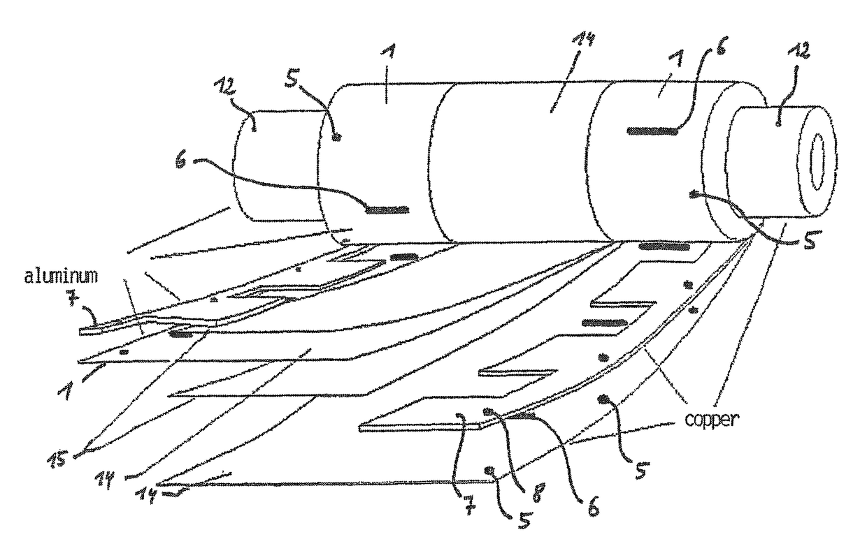
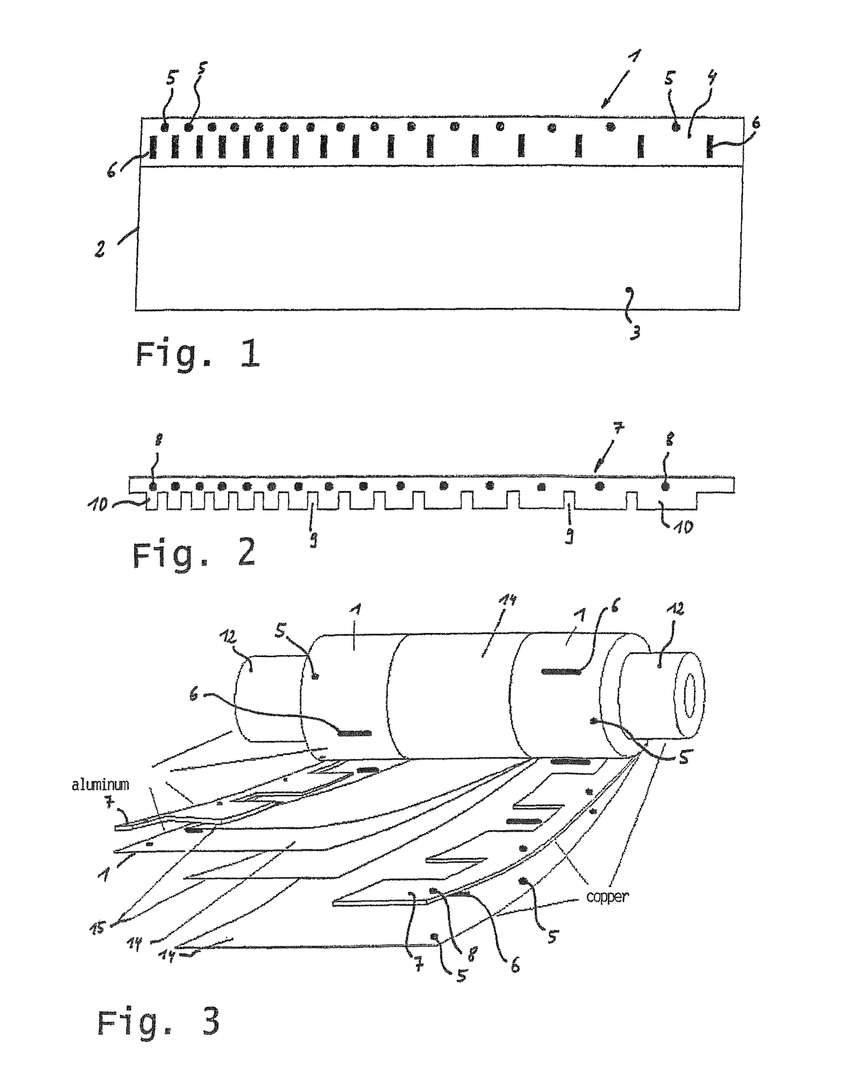
[0055]The winding packet of the lithium secondary cell array consists of copper and aluminium foils strips designed as shown in FIG. 1. Only the lower part 2 of the foil 1 is hereby coated on both sides with lithium and carbon black 3. An edge strip in the longitudinal direction 4 remains uncoated. In the free edge area there is a row of holes 5 and a row of slot-shaped breaches 6.

[0056]The holes and slots can be made by punching, whereby this punching process takes place before the coating of the lower part, simplifying the technological handling.

[0057]The gaps between the holes 5 and slots 6 is chosen such that in the finished foil winding, for example, six radial through holes and the same number of offset slots are produced.

[0058]Since the diameter of the winding increases with every layer, the gaps between the holes 5 and slots 6 increase from the inside to the outside (from left to right in FIG. 1). The gap to be observed can be easily dimensioned and technologically realised ...


PUM

PropertyMeasurementUnit
conductiveaaaaaaaaaa
areaaaaaaaaaaa
temperatureaaaaaaaaaa

Abstract

A lithium secondary cell array in a cylindrical design has a winding mandrel and a winding packet, which contains foil-like coated strips and contacting strips that form the electric cell structure consisting of anode, cathode and separator. The cell array has outer electrical connections which include pole caps. The winding mandrel includes an insulating material and has a through-channel extending in the longitudinal axis direction. The winding mandrel is connected to an inner pole cap at each end, the pole caps likewise having a respective through-channel. One outer pole cap having a through-passage is respectively provided, which surrounds the winding packet circumferentially at least in the edge region, wherein several radially arranged force-fit connections, each acting between the outer and the inner pole cap, are used to fix the winding packet and achieve the electrical contacting between the contacting strips and the outer pole cap.

Description

CROSS-REFERENCE TO RELATED APPLICATIONS[0001]Not ApplicableSTATEMENT REGARDING FEDERALLY SPONSORED RESEARCH OR DEVELOPMENT[0002]Not ApplicableTHE NAMES OF THE PARTIES TO A JOINT RESEARCH AGREEMENT[0003]Not ApplicableINCORPORATION-BY-REFERENCE OF MATERIAL SUBMITTED ON A COMPACT DISC OR AS A TEXT FILE VIA THE OFFICE ELECTRONIC FILING SYSTEM (EFS-WEB)[0004]Not ApplicableSTATEMENT REGARDING PRIOR DISCLOSURES BY THE INVENTOR OR A JOINT INVENTOR[0005]Not ApplicableBACKGROUND OF THE INVENTION[0006](1) Field of the Invention[0007]The invention relates to a lithium secondary cell array of a cylindrical design with a winding mandrel and a winding package, which contains foil-like, coated strips and contacting strips that form the electric cell structure consisting of the anode, cathode and separator, and having external electrical connecting means, these comprising pole caps in accordance with claim 1.[0008](2) Description of Related Art[0009]DE 696 36 796 T2 discloses a cylindrical secondary...

Claims


Application Information

Patent Timeline
Patent Type & Authority Patents(United States)
IPC IPC(8): H01M10/052H01M10/654H01M10/6567H01M10/643H01M10/0587H01M10/613H01M2/26H01M2/36H01M50/533H01M50/536H01M50/538H01M50/627
CPCH01M10/052H01M2/263H01M2/361H01M2/362H01M10/0587H01M10/613H01M10/643H01M10/654H01M10/6567H01M50/538H01M50/533H01M50/536H01M50/627Y02E60/10Y02P70/50
Inventor EBERT, KLAUSMEYER, STEFAN
Owner EBERT KLAUS
Why Eureka
Try Eureka