Eureka AIR delivers breakthrough ideas for toughest innovation challenges, trusted by R&D personnel around the world.

Wavelength control of an external cavity laser

Active Publication Date: 2017-05-16
ORACLE INT CORP
View PDF15 Cites 23 Cited by
  • Summary
  • Abstract
  • Description
  • Claims
  • Application Information

AI Technical Summary

Benefits of technology

The present patent describes an optical source that includes a semiconductor optical amplifier and a photonic chip. The optical source has a resonance wavelength that matches a cavity mode, and includes a reflective coating on the first edge and a ring resonator optically coupled to the second edge. The optical source also includes a first optical waveguide and a second optical waveguide, with a loop mirror that reflects a portion of the optical signal and passes the other portion in the third optical waveguide. The optical source also includes a first phase-tuning mechanism and a second phase-tuning mechanism to adjust the phase of the optical signal. The technical effect of this patent is to provide an optical source with improved stability and efficiency.

Problems solved by technology

However, tunable silicon photonic reflectors are often very sensitive to temperature changes.
During data transmission, wavelength optical mode-hops are essentially ‘glitches’ that can corrupt data transmitted, or may send data to the incorrect destination in a wavelength-division-multiplexed (WDM) system.
Consequently, optical mode-hopping is undesirable for digital communication links and typically needs to be reduced before a tunable hybrid external cavity laser may be effectively used for transmitting high-speed data across a range of wavelengths with good fidelity across the communication channel.
However, laser-power change due to other effects (such as laser-current change) can result in the wrong corrective action and, thus, the usefulness of this power-monitoring approach may be limited to situations where the optical power is not fluctuating.

Method used


Image

  • Wavelength control of an external cavity laser
  • Wavelength control of an external cavity laser
  • Wavelength control of an external cavity laser

Examples


Embodiment Construction

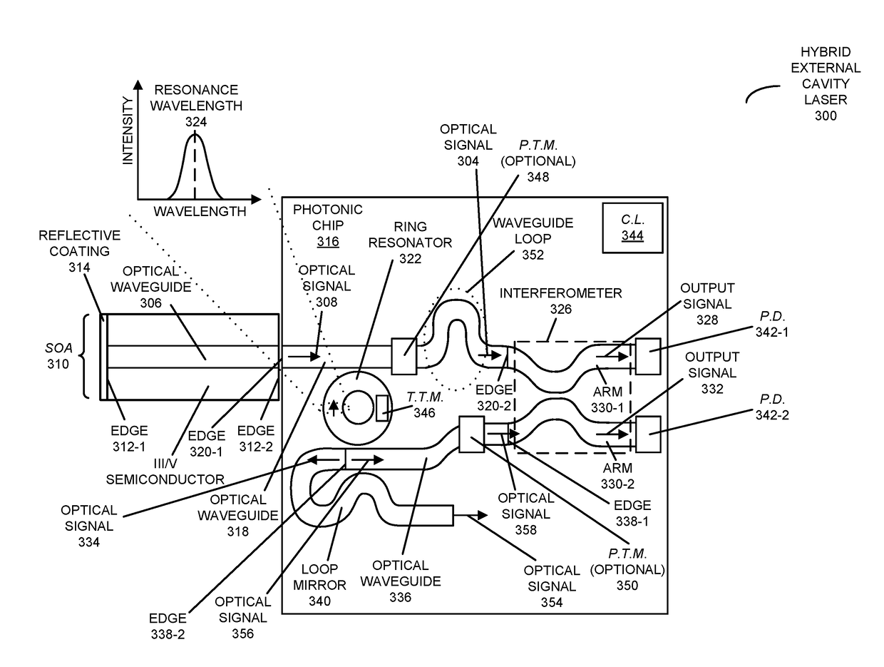
[0043]Embodiments of an optical source (such as a hybrid external cavity laser), a system that includes the hybrid external cavity laser, and a technique for locking a cavity mode for an external cavity laser are described. The hybrid external cavity laser includes a semiconductor optical amplifier (with a semiconductor other than silicon) that provides an optical gain medium and that includes a reflector (such as a mirror). Moreover, the hybrid external cavity laser includes a photonic chip with: an optical waveguide that conveys an optical signal output by the semiconductor optical amplifier; and a ring resonator (as a wavelength-selective filter), having a resonance wavelength, which reflects at least a resonance wavelength in the optical signal. Furthermore, the photonic chip includes an interferometer that provides optical signals on arms of the interferometer. Control logic in the hybrid external cavity laser thermally tunes the resonance wavelength to match a cavity mode of t...


PUM


Abstract

An optical source is described. This hybrid external cavity laser includes a semiconductor optical amplifier (with a semiconductor other than silicon) that provides an optical gain medium and that includes a reflector (such as a mirror). Moreover, the hybrid external cavity laser includes a photonic chip with: an optical waveguide that conveys an optical signal output by the semiconductor optical amplifier; and a ring resonator (as a wavelength-selective filter), having a resonance wavelength, which reflects at least a resonance wavelength in the optical signal. Furthermore, the photonic chip includes an interferometer that provides optical signals on arms of the interferometer. Control logic in the hybrid external cavity laser thermally tunes the resonance wavelength to match a cavity mode of the hybrid external cavity laser based on measurements of the optical signals from the interferometer.

Description

GOVERNMENT LICENSE RIGHTS[0001]This invention was made with U.S. government support under Agreement No. HR0011-08-9-0001 awarded by DARPA. The U.S. government has certain rights in the invention.BACKGROUND[0002]Field[0003]The present disclosure relates to the design of an optical source. More specifically, the present disclosure relates to the wavelength control of an external cavity laser with reduced optical mode-hopping.[0004]Related Art[0005]Silicon photonics is a promising technology candidate for dense, large-bandwidth interconnects for use in next-generation processing and computing systems. Considerable progress has been made to develop a comprehensive portfolio of optical components for such advanced intra / inter-system interconnects, including laser light sources.[0006]While a monolithic silicon light source remains elusive, silicon-assisted hybrid external cavity lasers have proven promising. A hybrid external cavity laser often includes a material section as an electrical...

Claims


Application Information

Patent Timeline
IPC IPC(8): H01S5/0687H01S3/106H01S5/14H01S5/10H01S3/10H01S5/026H01S5/30
CPCH01S5/0687H01S5/1071H01S5/14H01S3/1062H01S3/10053H01S5/3013H01S5/026H01S5/142H01S3/083H01S3/106
Inventor ZHENG, XUEZHELEE, DANIEL Y.KRISHNAMOORTHY, ASHOK V.
Owner ORACLE INT CORP
Why Eureka
Eureka Blog
Learn More