Laser light-source apparatus and laser pulse light generating method

a laser light source and laser pulse technology, applied in the direction of active medium materials, instruments, semiconductor lasers, etc., can solve the problems of only being able to produce lasers, difficult to appropriately control, and difficult to achieve long-term stable driving, so as to achieve the effect of immediately degrading the beam propagation characteristics

Active Publication Date: 2017-06-13
SPECTRONIX CORP
View PDF14 Cites 4 Cited by
  • Summary
  • Abstract
  • Description
  • Claims
  • Application Information

AI Technical Summary

Benefits of technology

[0041]As described above, the present invention can provide a laser light-source apparatus and a laser pulse light generating method in which when an output of pulse light from the apparatus is temporarily stopped while a seed light source is driven, a damage of a solid state amplifier, a nonlinear optical element, and the like can be prevented and thus degradation of beam propagation characteristics immediately after the output is resumed can be prevented, without stopping an excitation light source.

Problems solved by technology

Unfortunately, the mode-locked laser involves an oscillating frequency that is fluctuated by environmental factors such as temperature and vibration and thus is difficult to appropriately control.
Furthermore, long term stable driving is difficult to achieve because the mode-locked laser includes a saturable absorber, which is apt to degrade.
Unfortunately, the semiconductor laser is only capable of emitting near-infrared pulse light with extremely small pulse energy of several picojoules to several hundreds of picojoules.

Method used


Image

  • Laser light-source apparatus and laser pulse light generating method
  • Laser light-source apparatus and laser pulse light generating method
  • Laser light-source apparatus and laser pulse light generating method

Examples


Embodiment Construction

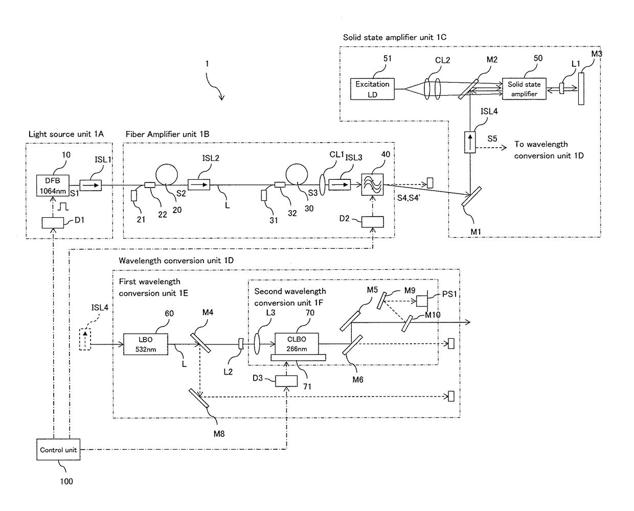
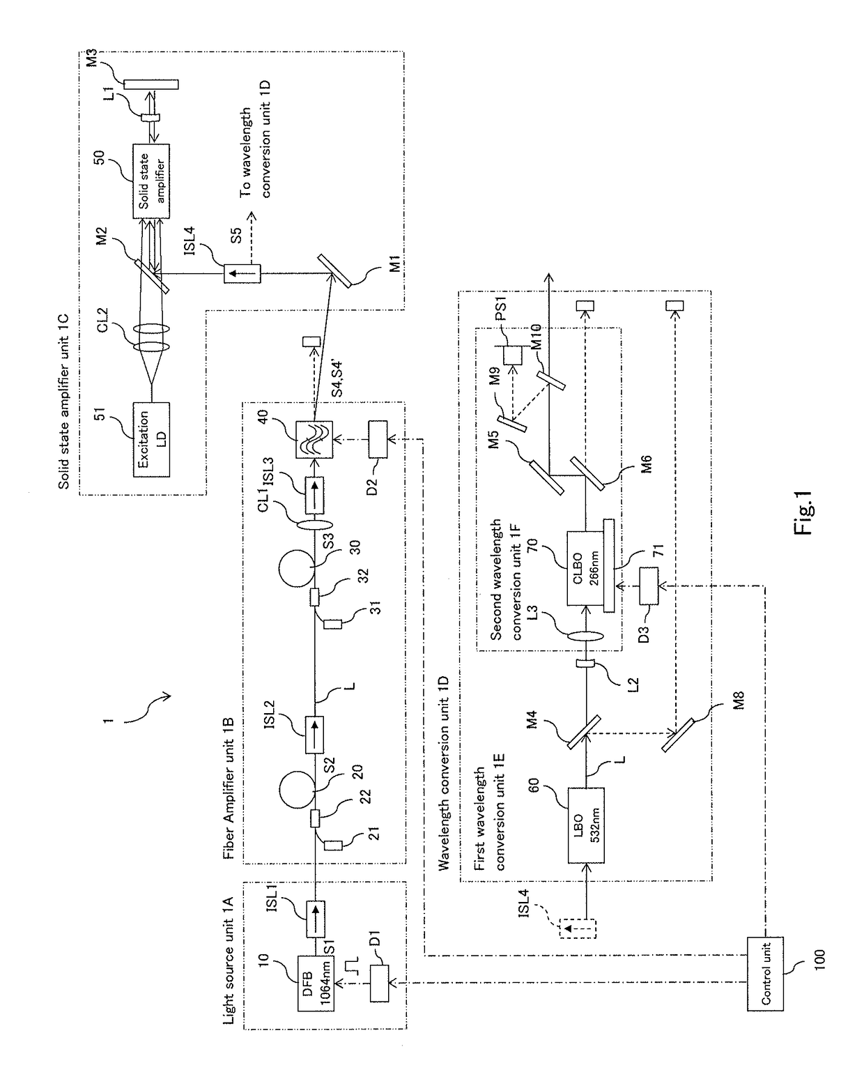
[0049]Embodiments of laser light-source apparatus and a laser pulse light generating method according to the present invention are described. FIG. 1 illustrates an example of a configuration of a laser light-source apparatus 1 according to the present invention. The laser light-source apparatus 1 includes a light source unit 1A, a fiber amplifier unit 1B, a solid state amplifier unit 1C, and a wavelength conversion unit 1D that are arranged along an optical axis L, and further includes a control unit 100 that controls the light source unit 1A and the like.

[0050]The light source unit 1A includes a seed light source 10, a seed light source driver D1, an optical isolator ISL1, and the like. The fiber amplifier unit 1B includes: fiber amplifiers 20 and 30, in two stages, respectively including excitation light sources 21 and 31, each including a laser diode, and multiplexers 22 and 32; optical isolators ISL2 and ISL3; an optical switching element 40; and the like.

[0051]The solid state a...


PUM

PropertyMeasurementUnit
wavelengthaaaaaaaaaa
oscillating frequencyaaaaaaaaaa
wavelengthaaaaaaaaaa

Abstract

A laser light-source apparatus includes: fiber amplifiers and a solid state amplifier configured to amplify pulse light output from a seed light source based on gain switching; nonlinear optical elements configured to perform wavelength conversion on the pulse light output from the solid state amplifier; an optical switching element configured to permit or stop propagation of pulse light from the fiber amplifier to the solid state amplifier; and a control unit configured to control the optical switching element in such a manner that the propagation of the light is stopped in an output period of the pulse light from the seed light source, and permitted in a period other than the output period of the pulse light from the seed light source.

Description

TECHNICAL FIELD[0001]The present invention relates to laser light-source apparatus and a laser pulse light generating method, used for various types of laser processing.BACKGROUND ART[0002]In recent years, laser light is used for various types of processing. Laser light with a wavelength approximately in a range from 532 nm to 1064 nm has a high energy intensity, and are suitably used for various types of processing such as cutting or welding of metal, glass, and the like. Laser light with a wavelength in a deep ultraviolet region, which is approximately from 200 nm to 350 nm, is used for processing electronic materials and composite materials.[0003]Laser light-source apparatus that outputs laser light with a wavelength shorter than those in a near-infrared region includes: a seed light source that outputs laser light having a wavelength in the near-infrared region; an optical amplifier that amplifies the laser light output from the seed light source; and a nonlinear optical element...

Claims


Application Information

Patent Timeline
Patent Type & Authority Patents(United States)
IPC IPC(8): H01S3/30H01S3/106H01S3/067H01S3/094H01S3/0941H01S3/10H01S3/16H01S3/23G02F1/37H01S3/131H01S5/12H01S3/108H01S3/00
CPCH01S3/106G02F1/37H01S3/0085H01S3/067H01S3/06758H01S3/09415H01S3/094076H01S3/10H01S3/10007H01S3/108H01S3/131H01S3/1611H01S3/1618H01S3/1643H01S3/2316H01S3/2375H01S5/12H01S3/0064H01S3/0092H01S3/2333H01S2301/02H01S3/094003H01S5/06216H01S3/1003H01S3/1001
Inventor OKADA, JOJIORII, YOSUKE
Owner SPECTRONIX CORP
Why Eureka
Try Eureka