Graphene-nano particle composite having nano particles crystallized therein at a high density

a nano-particle, composite technology, applied in the direction of carbon-silicon compound conductors, cell components, chemistry apparatus and processes, etc., can solve the problems of difficult to make use of a single-layer high specific surface area, difficult to form a uniform composite structure, and easy to peel off graphene in solution

Inactive Publication Date: 2017-07-25
CHEORWON PLASMA RES INST
View PDF10 Cites 0 Cited by
  • Summary
  • Abstract
  • Description
  • Claims
  • Application Information

AI Technical Summary

Benefits of technology

[0020]The graphene-nanoparticle composite according to the present invention exhibits excellent mechanical and electric characteristics since nanoparticles crystallized in a surface of graphene are included in a large amount to form chemical bonds at a high density. In particular, the graphene-nanoparticle composite may be widely used in the field of applications since the graphene-nanoparticle composite has an excellent electric conductivity of 1000 to 3000 S / m, and exhibits heat radiating characteristics, for example, a thermal conductivity of 5 to 30 W / mK.
[0022]In particular, the stacked structure may be effectively used in various electrochemical devices due to the excellent mechanical and electric characteristics. For example, the stacked structure may be applied to electrodes, electric elements, and thermoelectric materials, all of which include the graphene-nanoparticle composite or stacked structure thereof, and may also be used due to the thermal conductivity characteristics as a heat radiating material for extending the life span of display devices, lighting equipment such as LED, and electronic equipment such as computer parts.
[0030]In operation (c), the RF thermal plasma treatment may be performed by supplying an electric power of 10 to 70 kW. In preparation of the high-density graphene-nanoparticle composite according to the present invention, such RF thermal plasma treatment has various advantages.

Problems solved by technology

However, graphene is not easily peeled off in a solution due to the presence of van der Waals interaction between basal planes of graphene caused by a sp2 carbon bond formed on a surface of the graphene, and is present in the form of thick multilayer graphene other than single-layer graphene.
Therefore, graphene has problems in that it is impossible to make use of a high specific surface area of the single-layer graphene, and it is difficult to form a uniform composite structure.
Therefore, when graphene is applied to applied thermal or electric devices, an increase in thermal or electric contact resistance is caused according to a physical contact shape of a connection point between graphene and graphene, thereby inhibiting use of its innate high characteristics.
However, only the edge and defective parts of graphene are generally deposited when nanoparticles attempt to be deposited on graphene.
This wet process does not have an excellent effect of improving mechanical and electric characteristics of graphene since the nanoparticles are deposited on less than 10% of the surface of graphene.
Also, a chemical wet process method is used to forcibly form a defective part, but has problems in that it is difficult to optionally form a defective part at a certain position or several positions, and the original structure, that is, a hexagonal honeycomb lattice with a single bond, of graphene may be damaged when defects are formed at too many positions, thereby inhibiting electrochemical or thermal characteristics.

Method used


Image

  • Graphene-nano particle composite having nano particles crystallized therein at a high density
  • Graphene-nano particle composite having nano particles crystallized therein at a high density
  • Graphene-nano particle composite having nano particles crystallized therein at a high density

Examples


example 1

on and Characterization of Graphene-Tin (Sn) Nanoparticle Composite 1-1

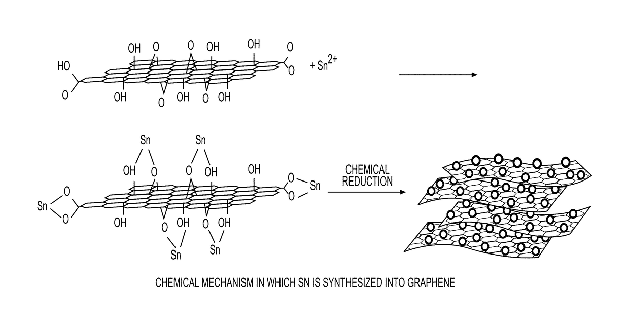
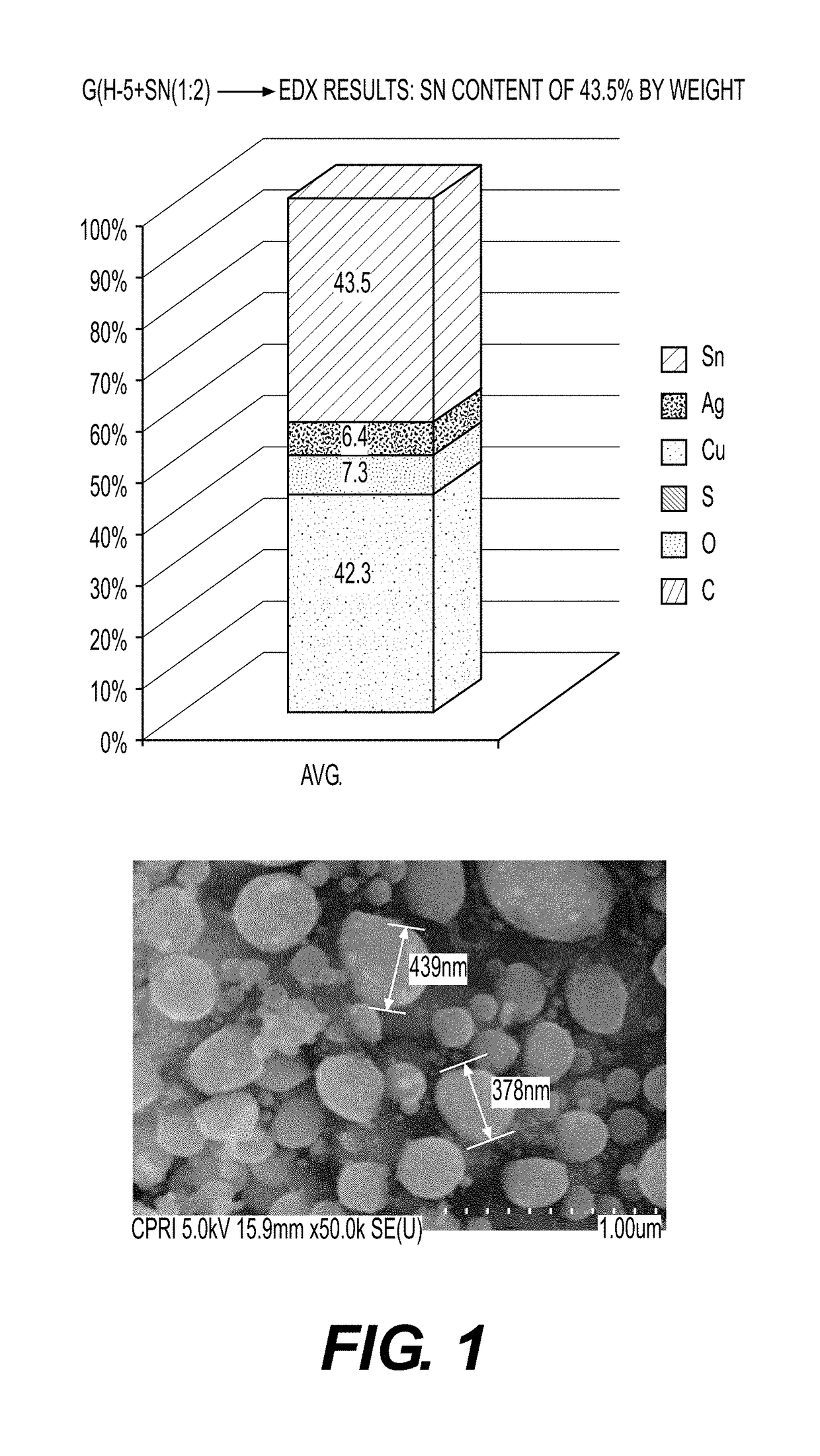
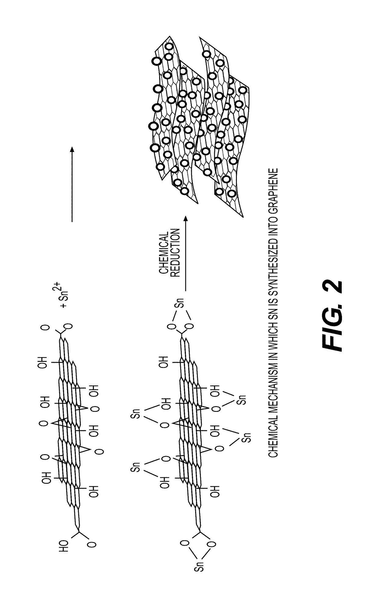
[0107]Preparation of graphene-Sn nanoparticle composite.

[0108]Graphene and tin (Sn) powder were mixed for 10 minutes at a mixing ratio of 1:2 to prepare a source powder, and 30 lpm and 50 lpm of argon gas were injected as the central gas and the sheath gas into a radio-frequency thermal plasma device for performing a preparation process according to the present invention. Then, this experiment was performed without injecting a quenching gas.

[0109]Subsequently, a voltage of 17 kW was applied to a power source of a plasma torch to produce high-temperature thermal plasma, and a degree of a vacuum in the device was maintained at 500 torr before injection of a source powder. Then, the source powder mixed with graphene was injected into a radio-frequency thermal plasma reaction unit through an injection nozzle of the plasma producing electrode unit 6, and the graphene in the radio-frequency thermal plasma reaction unit...

example 2

on and Characterization of Graphene-Silver (Ag) Nanoparticle Composite 2-1

[0117]Preparation of graphene-Ag nanoparticle composite.

[0118]Graphene and silver (Ag) powder were mixed at a mixing ratio of 4:1, 2:1, 1:1, and 1:1.5, and stirred for 10 minutes in a mixing machine to prepare a source powder. Then, a graphene-Ag nanoparticle composite was prepared in the same manner as in Example 1-1.

[0119]2-2. FE-SEM Imaging.

[0120]FIG. 4 shows FE-SEM imaging results (the same magnification of 50,000×) of the nanoparticle composite prepared according to a change in mixing ratio between graphene and Ag in the graphene-Ag nanoparticle composite prepared in Example 2-1. From the imaging results as shown in FIG. 4, it could be seen that the size of the silver nanopowder increased with an increase in mixing ratio of the powder. In particular, it was confirmed that silver did not increase a surface are of graphene, but increased the size of the particles bound to a surface graphene, unlike the othe...

experimental example 1

al Bonds

[0124]A graph showing the XRD analysis results capable of determining whether there are chemical bonds is shown in FIG. 3. For example, from the XRD analysis results on the composite of graphene and Sn, it was revealed that the peaks of Sn and C were observed, but the peak of Sn—C was not observed. This is because Sn preferentially binds to an O atom. Since a bond between Sn and O is preferentially formed in the synthetic product of graphene and Sn through the chemical bonds, the Sn—C peak was not observed from XRD.

[0125]As described above, the present invention relates to a graphene-nanoparticle composite having a structure in which nanoparticles are crystallized at a high density in a surface of graphene to form chemical bonds. Therefore, the graphene-nanoparticle composite exhibits excellent mechanical and electric characteristics since the nanoparticles are included at a large amount of 30% by weight or more, and have a high diameter of 200 nm or more. Accordingly, the g...


PUM

PropertyMeasurementUnit
particle diameteraaaaaaaaaa
electric conductivityaaaaaaaaaa
particle diameteraaaaaaaaaa

Abstract

The present invention relates to a graphene-nanoparticle composite having a structure in which nanoparticles are crystallized in a carbon-based material, for example, graphene, at a high density, and, more particularly, to a graphene-nanoparticle composite capable of remarkably improving physical properties such as contact characteristics between basal planes of graphene and conductivity, wherein nanoparticles are included as a large amount of 30% by weight or more, based on 100% by weight of graphene, and crystallized nanoparticles have an average particle diameter of 200 nm or more, and a method of preparing the same.

Description

CROSS-REFERENCE TO RELATED APPLICATION[0001]This application claims under 35 U.S.C. §119(a) the benefit of Korean Patent Application No. 2013-12743 filed on Feb. 5, 2013, the entire contents of which are incorporated herein by reference.BACKGROUND[0002]Technical Field[0003]The present disclosure relates to a graphene-nanoparticle composite having a structure in which nanoparticles are crystallized at a high density in a carbon-based material, for example, graphene, and, more particularly, to a graphene-nanoparticle composite capable of remarkably improving physical properties such as contact characteristics between basal planes of graphene and conductivity, wherein nanoparticles are included as a large amount of 30% by weight or more, based on the total amount of the composite, and crystallized nanoparticles have an average particle diameter of 200 nm or more, and a method of preparing the same.[0004]Background Art[0005]In recent years, interest in nanotechnology has been increasing...

Claims


Application Information

Patent Timeline
Patent Type & Authority Patents(United States)
IPC IPC(8): H01B1/04B82Y30/00
CPCC01B31/0484C01B2204/32C01B32/194Y02E60/10B82B1/00H01M4/133H01M4/134
Inventor KIM, STEVENSON, BYUNG-KOOSHIN, MYOUNG-SUNRYU, SUNG-HUNCHOI, SUN-YONGLEE, KYU-HANG
Owner CHEORWON PLASMA RES INST
Why Eureka
Try Eureka