Graphene-nano particle composite having nanoparticles crystallized therein at a high density

a nanoparticle and composite technology, applied in the field of graphenanoparticle composites, can solve the problems of difficult to form a uniform composite structure, difficult to use a high specific surface area of a single layer, and not easy to peel off graphene in a solution, etc., to achieve excellent electric conductivity, excellent mechanical and electric characteristics

Inactive Publication Date: 2015-06-25
CHEORWON PLASMA RES INST
View PDF2 Cites 31 Cited by
  • Summary
  • Abstract
  • Description
  • Claims
  • Application Information

AI Technical Summary

Benefits of technology

[0018]The graphene-nanoparticle composite according to the present invention exhibits excellent mechanical and electric characteristics since nanoparticles crystallized in a surface of graphene are included in a large amount to form chemical bonds at a high density. In particular, the graphene-nanoparticle composite may be widely used in the field of applications since the graphene-nanoparticle composite has an excellent electric conductivity of 1000 to 3000 S / m, and exhibits heat radiating characteristics, for example, a thermal conductivity of 5 to 30 W / mK. Also, the present invention provides a stacked structure obtained by stacking the high-density graphene-nanoparticle composite, and use thereof.
[0019]In particular, the stacked structure may be effectively used in various electrochemical devices due to the excellent mechanical and electric characteristics. For example, the stacked structure may be applied to electrodes, electric elements, and thermoelectric materials, all of which include the graphene-nanoparticle composite or stacked structure thereof, and may also be used due to the thermal conductivity characteristics as a heat radiating material for extending the life span of display devices, lighting equipment such as LED, and electronic equipment such as computer parts.

Problems solved by technology

However, graphene is not easily peeled off in a solution due to the presence of van der Waals interaction between basal planes of graphene caused by a sp2 carbon bond formed on a surface of the graphene, and is present in the form of thick multilayer graphene other than single-layer graphene.
Therefore, graphene has problems in that it is impossible to make use of a high specific surface area of the single-layer graphene, and it is difficult to form a uniform composite structure.
Therefore, when graphene is applied to applied thermal or electric devices, an increase in thermal or electric contact resistance is caused according to a physical contact shape of a connection point between graphene and graphene, thereby inhibiting use of its innate high characteristics.
However, only the edge and defective parts of graphene are generally deposited when nanoparticles attempt to be deposited on graphene.
This wet process does not have an excellent effect of improving mechanical and electric characteristics of graphene since the nanoparticles are deposited on less than 10% of the surface of graphene.
Also, a chemical wet process method is used to forcibly form a defective part, but has problems in that it is difficult to optionally form a defective part at a certain position or several positions, and the original structure, that is, a hexagonal honeycomb lattice with a single bond, of graphene may be damaged when defects are formed at too many positions, thereby inhibiting electrochemical or thermal characteristics.

Method used


Image

  • Graphene-nano particle composite having nanoparticles crystallized therein at a high density
  • Graphene-nano particle composite having nanoparticles crystallized therein at a high density
  • Graphene-nano particle composite having nanoparticles crystallized therein at a high density

Examples


example 1

Preparation and Characterization of Graphene-Nickel (Ni) Nanoparticle Composite

[0093]1-1. Preparation of Graphene-Ni Nanoparticle Composite

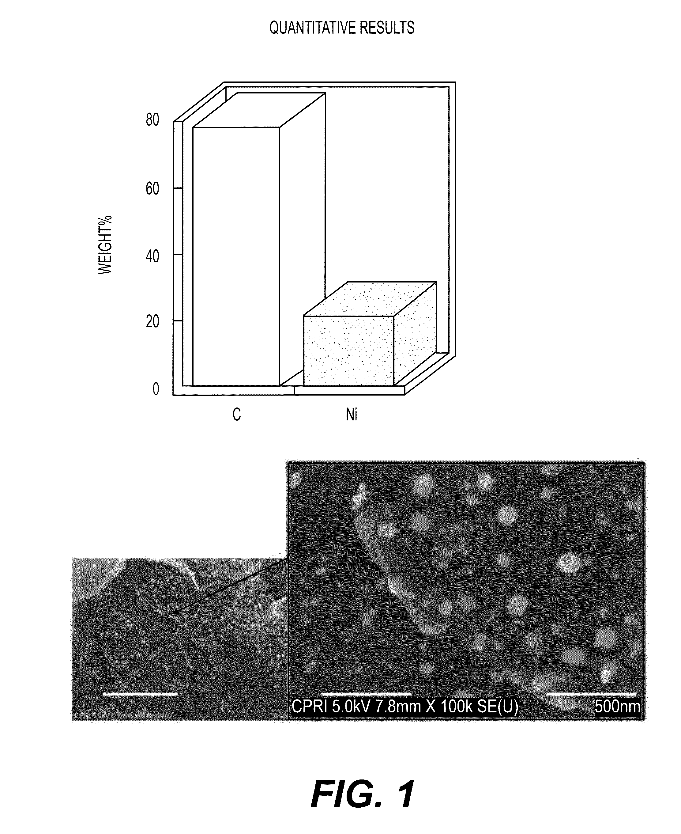
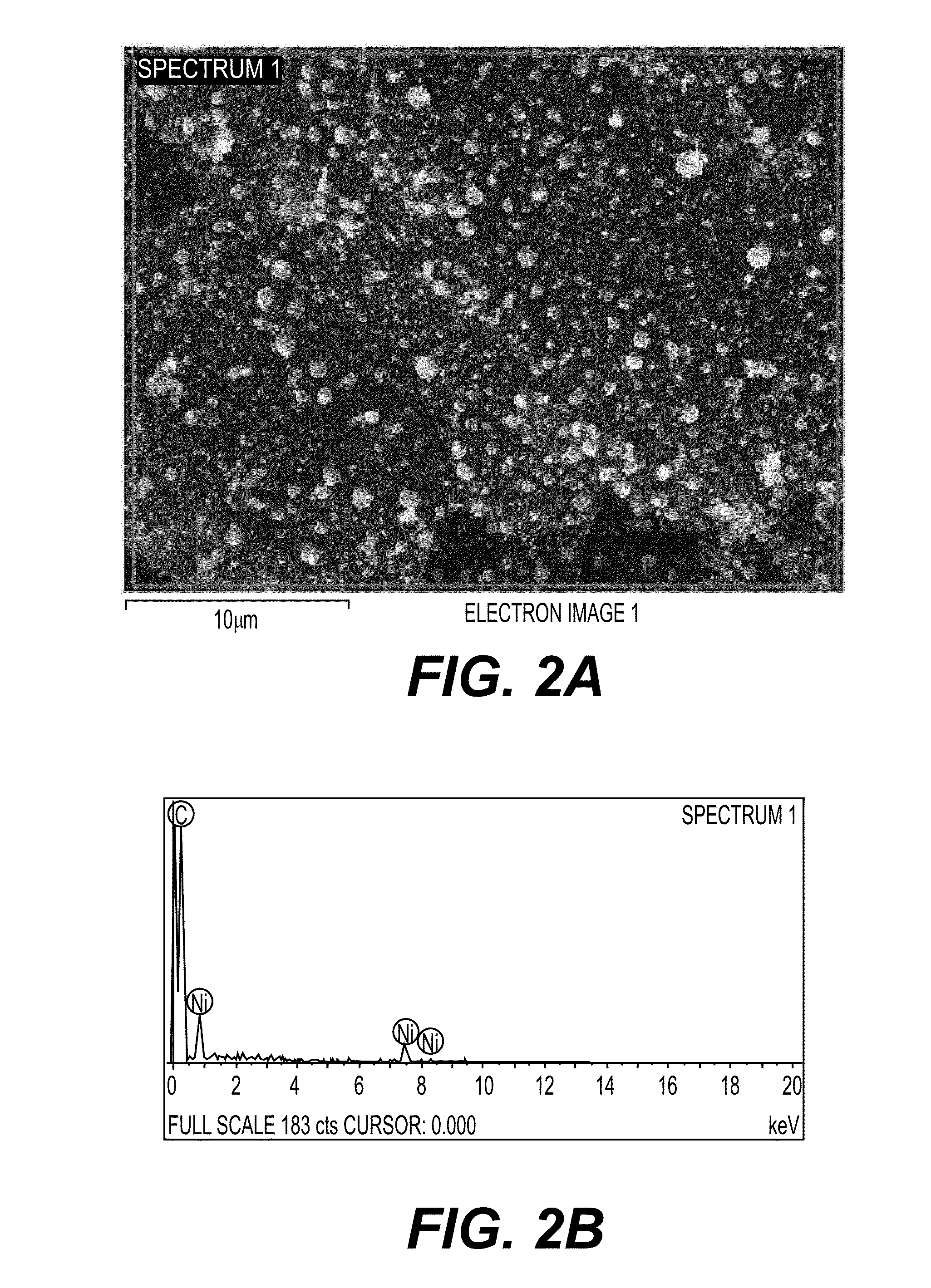
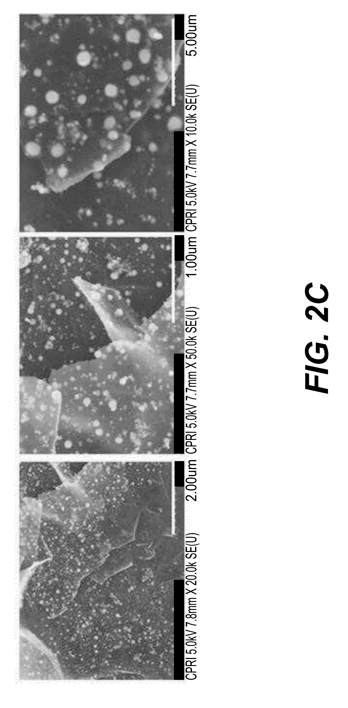
[0094]An increasing content (30% by weight, 40% by weight, and 50% by weight) of nickel (Ni) was mixed with graphene for 10 minutes using a mixing machine to prepare a source powder, and 30 lpm and 50 lpm of argon gas were injected as the central gas and the sheath gas into a radio-frequency thermal plasma device for performing a preparation process according to the present invention. Then, this experiment was performed without injecting a quenching gas.

[0095]Subsequently, a voltage of 17 kW was applied to a power source of a plasma torch to produce high-temperature thermal plasma, and a degree of a vacuum in the device was maintained at 500 torr before injection of a source powder. Then, the source powder mixed with graphene was injected into a radio-frequency thermal plasma reaction unit through an injection nozzle of the plasma producing elect...

example 2

Preparation and Characterization of Graphene-Silicon (Si) Nanoparticle Composite

[0115]2-1. Preparation of Graphene-Si Nanoparticle Composite

[0116]An increasing content (30% by weight, 40% by weight, and 50% by weight) of silicon (Si) was mixed with graphene for 10 minutes using a mixing machine to prepare a source powder, and a graphene-Si nanoparticle composite was prepared in the same manner as in Example 1-1. The results are shown in FIGS. 7 to 9.

[0117]2-2. FE-SEM Imaging

[0118]FIGS. 7A to 7F show the FE-SEM imaging results of the graphene-Si nanoparticle composite prepared in Example 2-1. The images shown in FIGS. 7A to 7F show the FE-SEM imaging results illustrating a change in density of Si bound to a surface of graphene when a content of Si was present at an increasing mixing ratio of 20% by weight, 40% by weight, and 60% by weight. From the FE-SEM imaging results, it could be seen that the Si nanopowder was fully fused with a surface of graphene, and that the density of the S...

example 3

Preparation and Characterization of Graphene-Silver (Ag) Nanoparticle Composite

[0124]3-1. Preparation of Graphene-Silver (Ag) Nanoparticle Composite

[0125]An increasing content (30% by weight, 40% by weight, and 50% by weight) of silver (Ag) was mixed with graphene for 10 minutes using a mixing machine to prepare a source powder, and a graphene-Ag nanoparticle composite was prepared in the same manner as in Example 1-1.

[0126]3-2. FE-SEM Imaging

[0127]FIGS. 10A and 10B show FE-SEM imaging results of the graphene-Ag nanoparticle composite prepared in Example 2-1. Referring to FIGS. 10A and 10B, it could be seen that silver particles are distributed at a high density on a surface of the graphene-Ag nanoparticle composite, which had a high particle diameter.

[0128]As described above, the present invention relates to a graphene-nanoparticle composite having a structure in which nanoparticles are crystallized at a high density in a surface of graphene to form chemical bonds. Therefore, the g...


PUM

PropertyMeasurementUnit
particle diameteraaaaaaaaaa
electric conductivityaaaaaaaaaa
electric poweraaaaaaaaaa

Abstract

The present invention relates to a graphene-nanoparticle composite having a structure in which nanoparticles are crystallized at a high density in a carbon-based material, for example, graphene, and, more particularly, to a graphene-nanoparticle composite capable of remarkably improving physical properties such as contact characteristics between basal planes of graphene and conductivity since nanoparticles are included as a large amount of 20 to 50% by weight, based on 100% by weight of graphene, and a method of preparing the same.

Description

BACKGROUND[0001]1. Technical Field[0002]The present disclosure relates to a graphene-nanoparticle composite having a structure in which nanoparticles are crystallized at a high density in a carbon-based material, for example, graphene, and, more particularly, to a graphene-nanoparticle composite capable of remarkably improving physical properties such as contact characteristics between basal planes of graphene and conductivity, wherein nanoparticles are included with a large amount of 20 to 50% by weight, based on the total amount of the composite, and a method of preparing the same.[0003]2. Background Art[0004]In recent years, interest in nanotechnology has been increasing with the rapid development of electronics, information-communication and biotechnology, and nanopowder has been increasingly expected to be applied to various applications such as high-strength machinery parts, catalytics, medicine and biotechnology, as well as electrics and electronics, since nanopowder exhibits...

Claims


Application Information

Patent Timeline
Patent Type & Authority Applications(United States)
IPC IPC(8): H01B1/04
CPCH01B1/04Y10T428/2982
Inventor KIM, STEVENSON, BYUNG-KOOSHIN, MYOUNG-SUNRYU, SUNG-HUNCHOI, SUN-YONGLEE, KYU-HANG
Owner CHEORWON PLASMA RES INST
Why Eureka
Try Eureka