
Steel material for nitriding and nitrided component

a technology of which is applied in the field of steel materials for nitriding and nitrided components, can solve the problems of poor machinability of steels for the said “induction quenching” and the large distortion of heat treatment, and achieves excellent machinability, high core hardness, and high surface hardness

Active Publication Date: 2017-08-01
NIPPON STEEL CORP
View PDF13 Cites 2 Cited by
  • Summary
  • Abstract
  • Description
  • Claims
  • Application Information

AI Technical Summary

Benefits of technology

The present invention relates to a new steel material that is excellent for nitriding, meaning it can be used to produce components that have high hardness and large effective case depth. The steel material is easy to machine and dispose of. The nitrided components made from this material also have excellent resistance to deformation, bending fatigue, and wear. This makes them ideal for use in machine structural components, such as gears and pulleys, for automobile transmissions.

Problems solved by technology

The “carburizing and quenching” has an advantage of attaining a high surface hardness and a large effective case depth, but this treatment is accompanied by phase transformation; and thus in the said treatment, there is a problem that the heat treating distortion becomes large.
In addition, the “carburizing and quenching” has a problem that a so-called “abnormal carburized layer”, which is an intergranularly oxidized layer, non-martensitic layer and so on, produced on the outer layer becomes a start point of failure such as bending fatigue failure, and the fatigue strength is deteriorated.
However, as for a starting material, the medium carbon steel has a higher hardness than the low carbon steel; and thus there is a problem that steels for the said “induction quenching” are inferior in machinability.
Unfortunately, the conventional steel material for nitriding has problems described in the following and .
Thus, the hardness of the starting material becomes high, and therefore the machinability is deteriorated.
With regard to the steel of this type, unfortunately, although a high surface hardness can be attained because Cr, Al and the like produce nitrides near the surface, a high bending fatigue strength cannot be attained because of a shallow effective case depth.

Method used


Image

  • Steel material for nitriding and nitrided component
  • Steel material for nitriding and nitrided component
  • Steel material for nitriding and nitrided component

Examples


examples

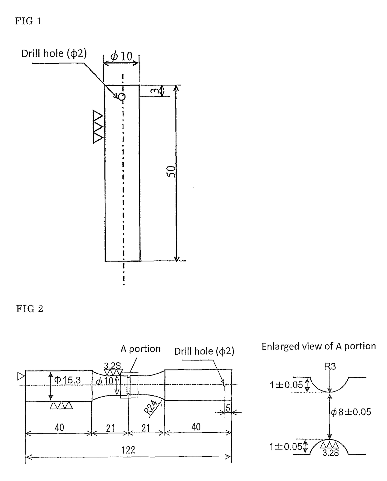
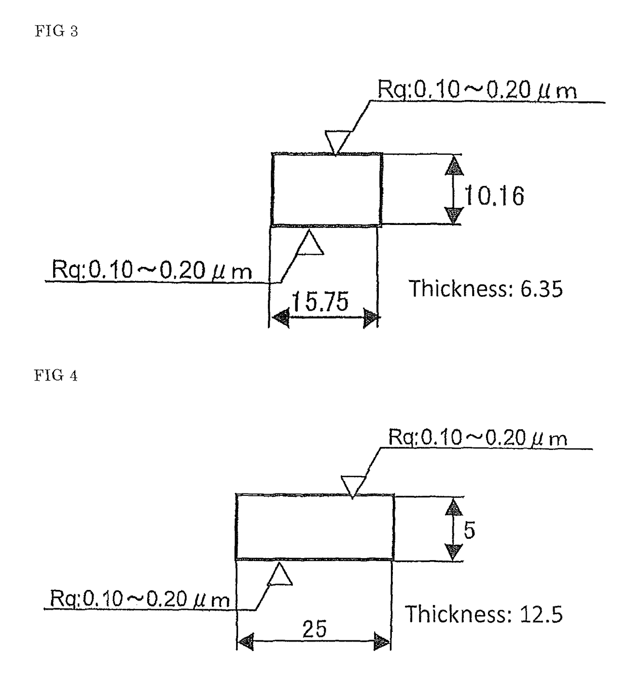
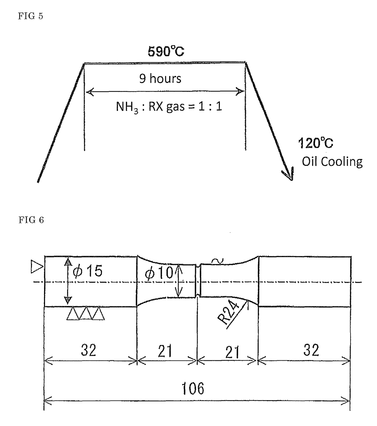
[0161]The steels 1 to 19 having the chemical compositions shown in Table 1 were melted by using a 180 kg vacuum melting furnace and cast to ingots.

[0162]The steels 1 to 13 and 19 shown in Table 1 are steels with chemical compositions being within the range regulated by the present invention. On the other hand, the steels 14 to 18 are steels of comparative examples with chemical compositions being out of the range regulated by the present invention. Note that, with respect to Mo and V in the Fn1 expressed by the formula (1) and V in the Fn2 expressed by the formula (2), each symbol “-” in Table 1 indicates “0 (zero)”.

[0163]Among the steels of comparative examples mentioned above, the steel 14 is a steel corresponding to the SCr420H specified in JIS G 4052 (2008).

[0164]

TABLE 1Chemical composition (% by mass) Balance: Fe and impuritiesSteelCSiMnPSCuNiCrMoAlVNOOthersFn1Fn210.180.080.900.0080.012——1.21—0.0350.180.00570.0012Zr: 0.048,   53216Te: 0.002520.160.090.620.0090.009——0.920.080.02...


PUM

PropertyMeasurementUnit
temperatureaaaaaaaaaa

Abstract

A steel material for nitriding has a composition comprising, by mass percent, C: more than 0.15% and not more than 0.35%, Si≦0.20%, Mn: 0.10 to 2.0%, P≦0.030%, S≦0.050%, Cr: 0.80 to 2.0%, V: 0.10 to 0.50%, Al: 0.01 to 0.06%, N≦0.0080%, O≦0.0030%, and optionally one or more elements of Mo, Cu, Ni, Ti, Nb, Zr, Pb, Ca, Bi, Te, Se and Sb, the balance being Fe and impurities. The composition satisfies the conditions of [20≦(669.3×logeC−1959.6×logeN−6983.3)×(0.067×Mo+0.147×V)≦80] and [140×Cr+125×Al+235×V≧160]. The microstructure is a ferritic-pearlitic structure, a ferritic-bainitic structure, or a ferritic-pearlitic-bainitic structure. The area fraction of ferrite is 20% or more and the precipitate content of V is 0.10% or less.

Description

TECHNICAL FIELD[0001]The present invention relates to a steel material for nitriding and nitrided component. More specifically, the present invention relates to a steel material for nitriding which is excellent in machinability, particularly in chip disposability, and also can provide a component subjected to a nitriding treatment with high core hardness, high surface hardness and a large effective case depth, and is used suitably as a starting material for a nitrided component, and in addition relates to a nitrided component using the same.[0002]The “nitriding” in the present invention is a treatment including the “nitrocarburizing” treatment in which “N and C are caused to invade and diffuse”, not merely the “nitriding” treatment in which “N is caused to invade and diffuse”. Therefore, in the explanation below, a treatment including the “nitrocarburizing” is referred simply to as the “nitriding”.BACKGROUND ART[0003]A component for machine structural use that is used for an automob...

Claims


Application Information

Patent Timeline
Patent Type & Authority Patents(United States)
IPC IPC(8): C23C8/26C21D1/06C23C8/32C22C38/00C22C38/02C22C38/04C22C38/06C22C38/20B32B15/18C22C38/24C22C38/40C22C38/26C22C38/28C22C38/38C22C38/42C22C38/46C22C38/60C22C38/50C21D9/32C23C8/50C23C8/38C22C38/22
CPCC22C38/26C22C38/28C22C38/38C22C38/40C22C38/42C22C38/46B32B15/18C21D1/06C22C38/001C22C38/002C22C38/02C22C38/04C22C38/06C22C38/20C22C38/22C22C38/24C22C38/50C22C38/60C23C8/26C23C8/32C23C8/38C23C8/50C21D9/32C21D2211/002C21D2211/005C21D2211/009Y02P10/212Y02P10/20
Inventor GYOTOKU, YUYAHORIMOTO, MASAYUKIIMATAKA, HIDEKITANAKA, KOSUKE
Owner NIPPON STEEL CORP
Learn More