Polarizing plate protective film, dope composition, method for manufacturing polarizing plate protective film, polarizing plate, and liquid crystal display device

a technology of polarizing plate and protective film, which is applied in the direction of polarizing elements, instruments, other domestic articles, etc., can solve the problems of step-like unevenness and insufficient heat resistance of polarizing plate protective film, and achieve excellent heat resistance and excellent surface shape , the effect of efficient polarization

Active Publication Date: 2017-09-05
FUJIFILM CORP
View PDF12 Cites 2 Cited by
  • Summary
  • Abstract
  • Description
  • Claims
  • Application Information

AI Technical Summary

Benefits of technology

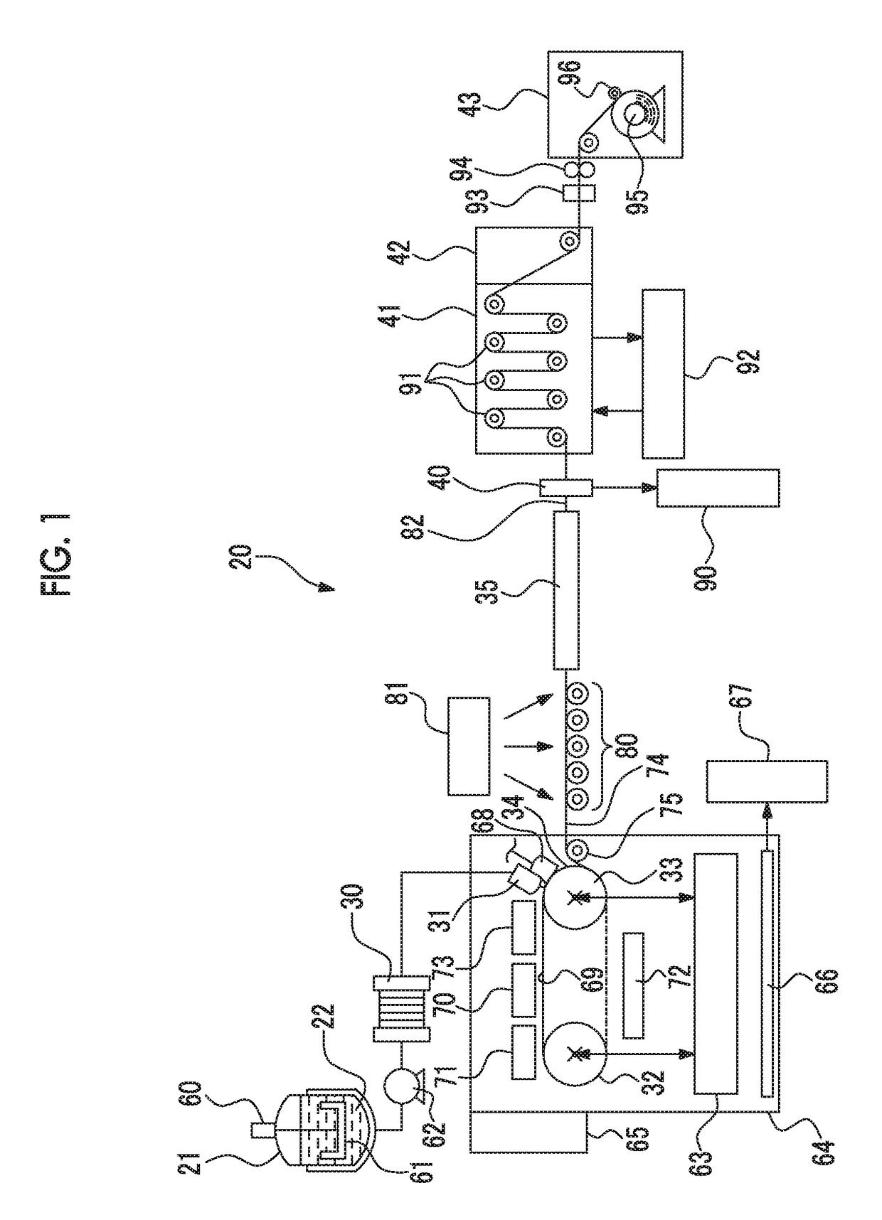
[0011]Therefore, in order to solve the problems of the related art, the present inventors have conducted studies for providing a polarizing plate protective film having excellent heat resistance and an excellent surface shape. Further, the present inventors have conducted studies for providing a method for manufacturing a polarizing plate protective film with high productivity, a dope composition used therein, and a polarizing plate and a liquid crystal display device comprising the polarizing plate protective film.
[0027]According to the polarizing plate protective film and the method for manufacturing thereof of the present invention, it is possible to efficiently obtain a polarizing plate protective film having excellent heat resistance and an excellent surface shape.
[0028]In addition, according to the polarizing plate and the liquid crystal display device of the present invention, warping rarely occurs even under a high temperature environment, excellent display properties are able to be obtained, and high productivity is able to be obtained by using the polarizing plate protective film of the present invention.

Problems solved by technology

However, the present inventors have performed actual evaluation with respect to a polarizing plate protective film using the acrylic resin of the related art, and thus, have found that the polarizing plate protective film has insufficient heat resistance, the polarizing plate protective film was deformed in a case of being left to stand under a high temperature environment such as the inside of a vehicle in summer, and a polarizing plate and the entire panel warped according to the deformation.
In addition, even in a manufacturing step thereof, it is necessary to set an acrylic resin solution to have a comparatively high concentration in order to subject to solution film formation in an acrylic resin having a comparatively low molecular weight of 80,000 to 150,000, and in this case, it was obvious that streaks occurred on the surface of a casting film at the time of being ejected from a casting die, and step-like unevenness also occurred on the surface of a film to be obtained.

Method used


Image

  • Polarizing plate protective film, dope composition, method for manufacturing polarizing plate protective film, polarizing plate, and liquid crystal display device
  • Polarizing plate protective film, dope composition, method for manufacturing polarizing plate protective film, polarizing plate, and liquid crystal display device

Examples


manufacturing example 1

[0213]An acrylic resin (a PMMA resin) having a weight average molecular weight of 1,300,000, an MMA ratio of 100%, an MA ratio of 0%, and a heating loss of 0.10% which was used in Examples 1 and 101 to 106, and Comparative Examples 101 to 107 was synthesized by the following method.

[0214]300 g of ion exchange water and 0.6 g of polyvinyl alcohol (a degree of saponification of 80% and a degree of polymerization of 1,700) were added to a three-neck flask of 1 L to which a mechanical stirrer, a thermometer, and a cooling pipe were attached and were stirred, the polyvinyl alcohol was completely dissolved, and then, 100 g of methyl methacrylate and 0.15 g of azo bisisobutyronitrile were added and reacted with each other at 85° C. for 6 hours. The obtained suspension liquid was filtered through nylon filter cloth and was washed with methanol, a filtrate was dried all night at 50° C., and thus, an aimed polymer was obtained in the shape of a bead (92.0 g).

manufacturing example 2

[0215]An acrylic resin having a weight average molecular weight of 1,300,000, an MMA ratio of 100%, an MA ratio of 0%, and a heating loss of 0.30% which was used in Example 5 was synthesized by the following method.

[0216]An aimed polymer was obtained in the shape of a bead by the same method as that in Manufacturing Example 1 except that methanol washing was not performed (90.0 g).

manufacturing example 3

[0217]An acrylic resin having a weight average molecular weight of 1,300,000, an MMA ratio of 100%, an MA ratio of 0%, and a heating loss of 1.0% which was used in Comparative Example 3 was synthesized by the same method as that in Manufacturing Example 2 except that an initiator was changed to benzoyl peroxide.

Other Manufacturing Examples

[0218]An acrylic resin having a weight average molecular weight of 800,000, an MMA ratio of 100%, an MA ratio of 0%, and a heating loss of 0.10% which was used in Example 2 was synthesized by the same method as that in Manufacturing Example 1 except that a reaction time was set to 3 hours.

[0219]An acrylic resin having a weight average molecular weight of 500,000, an MMA ratio of 100%, an MA ratio of 0%, and a heating loss of 0.10% which was used in Example 3 was synthesized by the same method as that in Manufacturing Example 1 except that a reaction time was set to 2 hours.

[0220]An acrylic resin having a weight average molecular weight of 100,000, ...


PUM


Abstract

A polarizing plate protective film containing an acrylic resin, in which the acrylic resin includes a methyl methacrylate unit a, a mass fraction of an alkyl (meth)acrylate unit b other than methyl methacrylate is less than 5 mass %, a weight average molecular weight is 250,000 to 4,000,000, and a weight decreasing amount at the time of being heated at 140° C. for 1 hour is less than or equal to 0.5%, has excellent heat resistance and an excellent surface shape; a dope composition; a method for manufacturing a polarizing plate protective film; a polarizing plate; and a liquid crystal display device.

Description

CROSS-REFERENCE TO RELATED APPLICATIONS[0001]This application is a Continuation of PCT International Application No. PCT / JP2014 / 079022, filed on Oct. 31, 2014, which was published under PCT Article 21(2) in Japanese, and claims priority under 35 U.S.C. Section 119(a) to Japanese Patent Application No. 2013-228733 filed on Nov. 1, 2013. The above applications are hereby expressly incorporated by reference, in their entirety, into the present application.BACKGROUND OF THE INVENTION[0002]1. Field of the Invention[0003]The present invention relates to a polarizing plate protective film, a dope composition, a method for manufacturing a polarizing plate protective film, a polarizing plate, and a liquid crystal display device.[0004]2. Description of the Related Art[0005]A demand for using a liquid crystal display device as a liquid crystal display or the like of a liquid crystal television or a personal computer has increased. In general, a liquid crystal display device is configured of a ...

Claims


Application Information

Patent Timeline
Patent Type & Authority Patents(United States)
IPC IPC(8): C08J5/18B29D7/01B29C69/00B29C55/14B29C41/00G02B1/14G02B5/30C08F220/14C08L33/12B29C55/00B29C41/02G02F1/1335B29K33/00B29K105/00B29K105/16
CPCC08J5/18B29C41/003B29C41/02B29C55/005B29C55/143B29C69/00B29D7/01C08F220/14C08L33/12G02B1/14G02B5/3033B29K2033/12B29K2105/0058B29K2105/16B29K2105/256B29K2995/0017C08J2333/12G02F1/133528
Inventor SASATA, KATSUMINAKAYAMA, HAJIMEARITA, SHUSUKENOZOE, YUTAKA
Owner FUJIFILM CORP
Why Eureka
Try Eureka