Swept source OCT system and method with phase-locked detection

a phase-locked detection and swept source technology, applied in the field of medical imaging, can solve the problems of increasing blurry 2d image in fig. 4, position shift, surprising severe blurriness problems, etc., and achieve the effect of high wavelength sweep ra

Active Publication Date: 2017-10-10
LUDWIG MAXIMILIANS UNIV MUNCHEN
View PDF11 Cites 12 Cited by
  • Summary
  • Abstract
  • Description
  • Claims
  • Application Information

AI Technical Summary

Benefits of technology

[0020]The invention is based on the objective of disclosing a swept-source OCT system and a swept-source OCT method that allow the use of high wavelength sweep rates and still produce images with sound image quality.
[0037]Furthermore, the system preferably comprises a scanning device, by means of which the sample beam can be scanned over a sample, wherein the scanning device is activated by a scanning signal that is phase-locked with the sweep control signal. Such scanning devices may comprise, for example, deflection mirrors that are operated with galvanomanometric motors or so-called “galvos.” Other examples are spiral scan catheters suitable for intravascular OCT or polygon scanners. Resonant scanners frequently allow high scanning speeds, but often have only a relatively narrow resonance range that needs to be taken into consideration in the phase-locking. This can lead to the frequency of the sweep control signal and of the scanning signal not necessarily being integrally related, but this is not absolutely imperative for the purpose of phase-locking. In fast OCT systems, the imaging beam is frequently moved over the sample so fast that the beam advances by about one beam diameter per depth scan. If the scanner is not phase-locked, the start of the scanning phases therefore can only be determined with an accuracy of ±1 sweep of the tunable light source such that the position of the first depth scan is not exactly defined in the scanning direction, but rather subject to some uncertainty. In a 3D scan, this can lead to “zipper artifacts,” particularly if the image contains structures that lie perpendicular to the fast scanning direction. The OCT data sets furthermore can thusly be reproduced in a superior fashion. This is particularly advantageous with respect to averaging methods such as, for example, the so-called “volume averaging” in order to prevent “smearing” of the averaged image.
[0038]In an advantageous enhancement, the swept-source OCT system comprises a synchronization unit that is designed for generating a data frame start signal or a data volume start signal that is synchronized with the scanning device or with the scanning signal and phase-locked with the sweep control signal. For example, this synchronization unit may generate the data frame start signal or the data volume start signal at a point in time, at which the scanning device is in the correct location. Additional trigger jitter can be prevented because this signal is furthermore phase-locked with the sweep control signal. If a buffered tunable light source is used, it is advantageous to synchronize the frame start or volume start with a special sweep such as, e.g., the primary sweep, the first buffered sweep, etc., such that the resampling and the subtraction of the background are simplified.
[0047]In contrast to customary methods known from the prior art, the k-clock is in this case not derived from the optical signal, but rather generated entirely “artificially,” for example in a digital fashion, based on an input signal that is phase-locked with the sweep control signal. In this context, the term “artificially generated” is merely intended to express that the signal is not directly derived from the optical signal. Although the artificially or electronically generated k-clock signal consists of clock pulse edges with time-variable intervals, it is in accordance with the parlance of the present disclosure considered as being phase-locked with the sweep control signal because the input signal of the k-clock generator is phase-locked with the sweep control signal. The timing of the digitally generated k-clock preferably is once again chosen such that the sampling points defined by the k-clock signal are at least approximately equidistant in the optical frequency of the interference signal in order to eliminate the need for resampling.

Problems solved by technology

The inventors have furthermore discovered that very slight variations in the ratio between fscan and fsamp already lead to surprisingly severe blurriness problems of the type illustrated in FIG. 4.
This causes the phase position to shift during resampling such that the 2D image in FIG. 4 becomes increasingly blurry along the scanning direction.
However, such slight fluctuations in the ratio between fsweep and fsamp are difficult to avoid and it is at first sight surprising that they have such a significant effect on the image quality.

Method used


Image

  • Swept source OCT system and method with phase-locked detection
  • Swept source OCT system and method with phase-locked detection
  • Swept source OCT system and method with phase-locked detection

Examples


Embodiment Construction

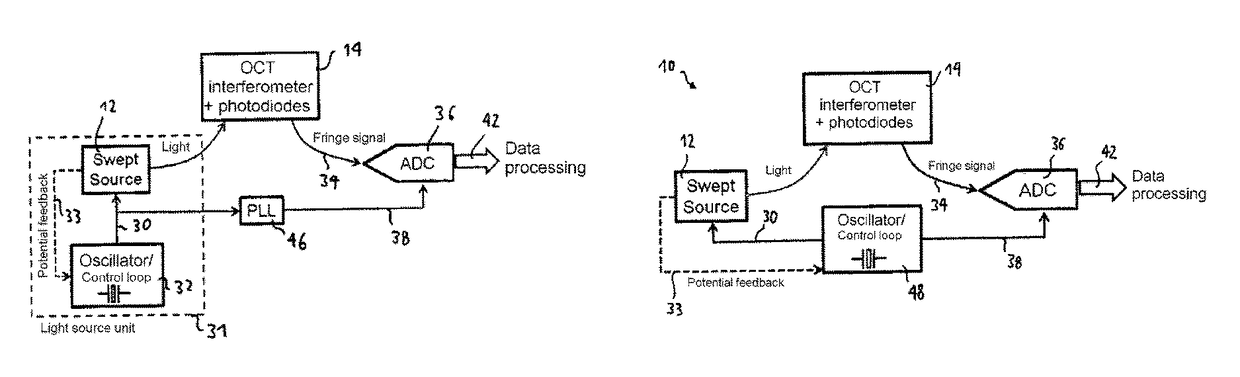
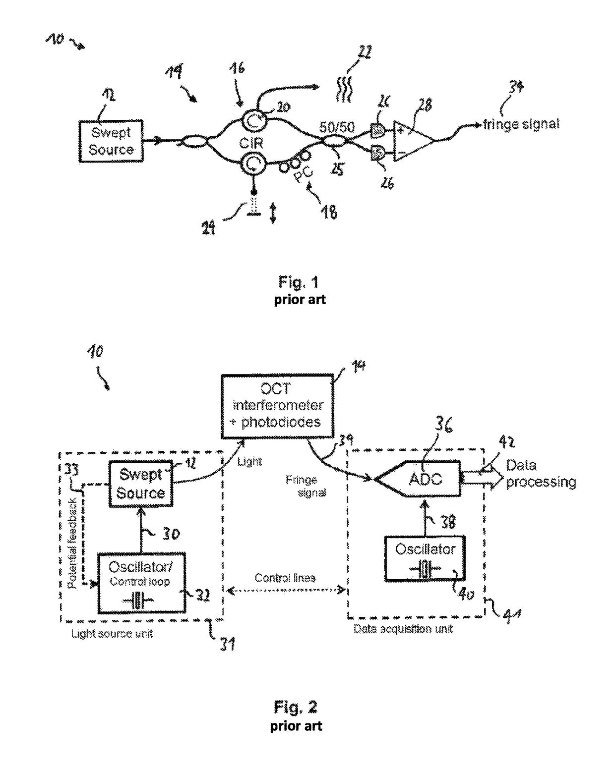
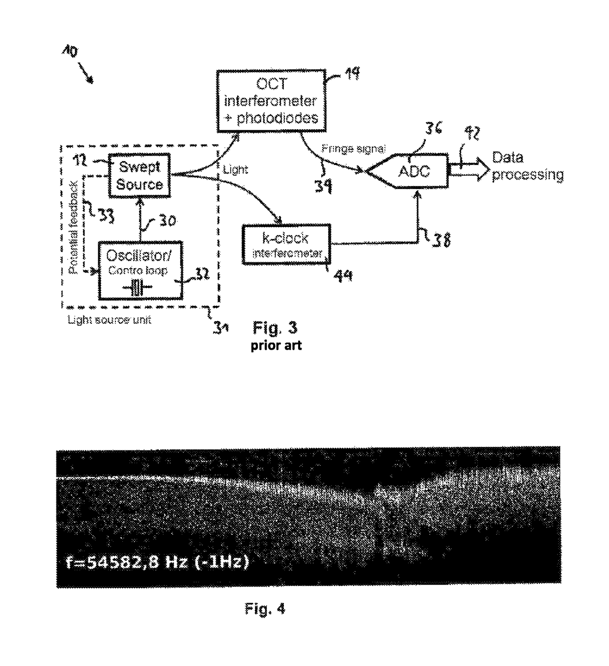
[0066]FIG. 6a shows the schematic design of a swept-source OCT system 10 according to the invention. The swept-source OCT system essentially consists of the same components as the system in FIG. 2, wherein these components are not described anew and identified by the same reference symbols. The essential difference can be seen in that a phase-locked loop (PLL) 46 is provided, by means of which a detection clock signal 38 is derived from the sweep control signal 30, wherein this detection clock signal has a frequency that amounts to a multiple of the frequency of the sweep control signal 30 and is phase-locked therewith. For example, the sweep control signal 30 may have a frequency of 1 MHz that corresponds to the repetition rate fsweep of the tunable light source 12, whereas the detection clock signal may have a frequency of 1 GHz. In this case, a phase-locked detection clock signal 38 is derived from the sweep control signal 30 with the aid of the PLL 46, wherein the frequency of t...


PUM


Abstract

A swept source OCT system and related method are disclosed. The system comprises a control device for operating a tunable light source in response to an electronic sweep control signal such that the tunable light source carries out wave length sweeps with a repetition rate fsweep, which depends on the frequency of the sweep control signal. The system further comprises a detection device for the time-resolved detection of an interference signal from a sample beam and a reference beam with the help of a detection cycle signal. The sweep control signal and the detection cycle signal are phase-locked, or means for creating a signal or signal sequence are provided, said signal or signal sequence being characterising for the frequency relationship and / or the relative phase position of the sweep control signal and detection cycle signal.

Description

FIELD OF THE INVENTION[0001]The present invention pertains to the field of medical imaging. It particularly pertains to a swept-source OCT system and a swept-source OCT method, as well as an OCT-based photoacoustic detection method.BACKGROUND AND RELATED PRIOR ART[0002]Optical coherence tomography (OCT) is an optical method, by means of which 3D images of optically scattering media such as, for example, biological tissue can be recorded with a resolution in the micrometer range. In this case, the depth direction of the sample, i.e. the dimension along the irradiating direction of a sample beam, is captured in that—in simplified terms—the distance of scattering centers within the sample from the light source is measured by means of interferometric signals. Light with a comparatively long wavelength, typically in the near-infrared range, is used in OCT. This has the advantage that the light can penetrate comparatively deep into the scattering medium such that its scans sections can be...

Claims


Application Information

Patent Timeline
Patent Type & Authority Patents(United States)
IPC IPC(8): G01B9/02
CPCG01B9/02004G01B9/0203G01B9/02091G01B9/02069G01B9/02043
Inventor HUBER, ROBERT ALEXANDERKLEIN, THOMASWIESER, WOLFGANG
Owner LUDWIG MAXIMILIANS UNIV MUNCHEN
Why Eureka
Try Eureka