Component cooling water system for nuclear power plant

a technology for cooling water systems and nuclear power plants, applied in nuclear engineering, nuclear elements, greenhouse gas reduction, etc., can solve the problems of rapid rise of pressure and temperature in the containment space, reactors becoming a “scram”, and the installation of a large capital requirement such as a steam generator is extremely difficult and expensive, so as to prevent warping

Active Publication Date: 2017-10-10
SMR INVENTEC
View PDF29 Cites 2 Cited by
  • Summary
  • Abstract
  • Description
  • Claims
  • Application Information

AI Technical Summary

Benefits of technology

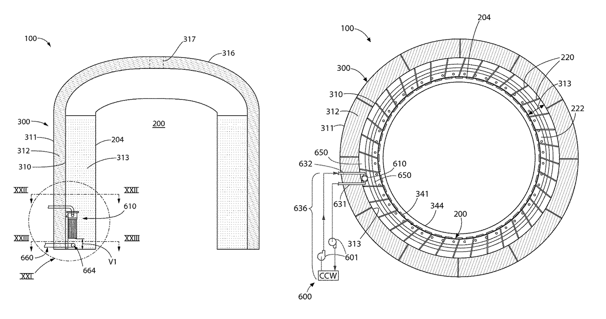
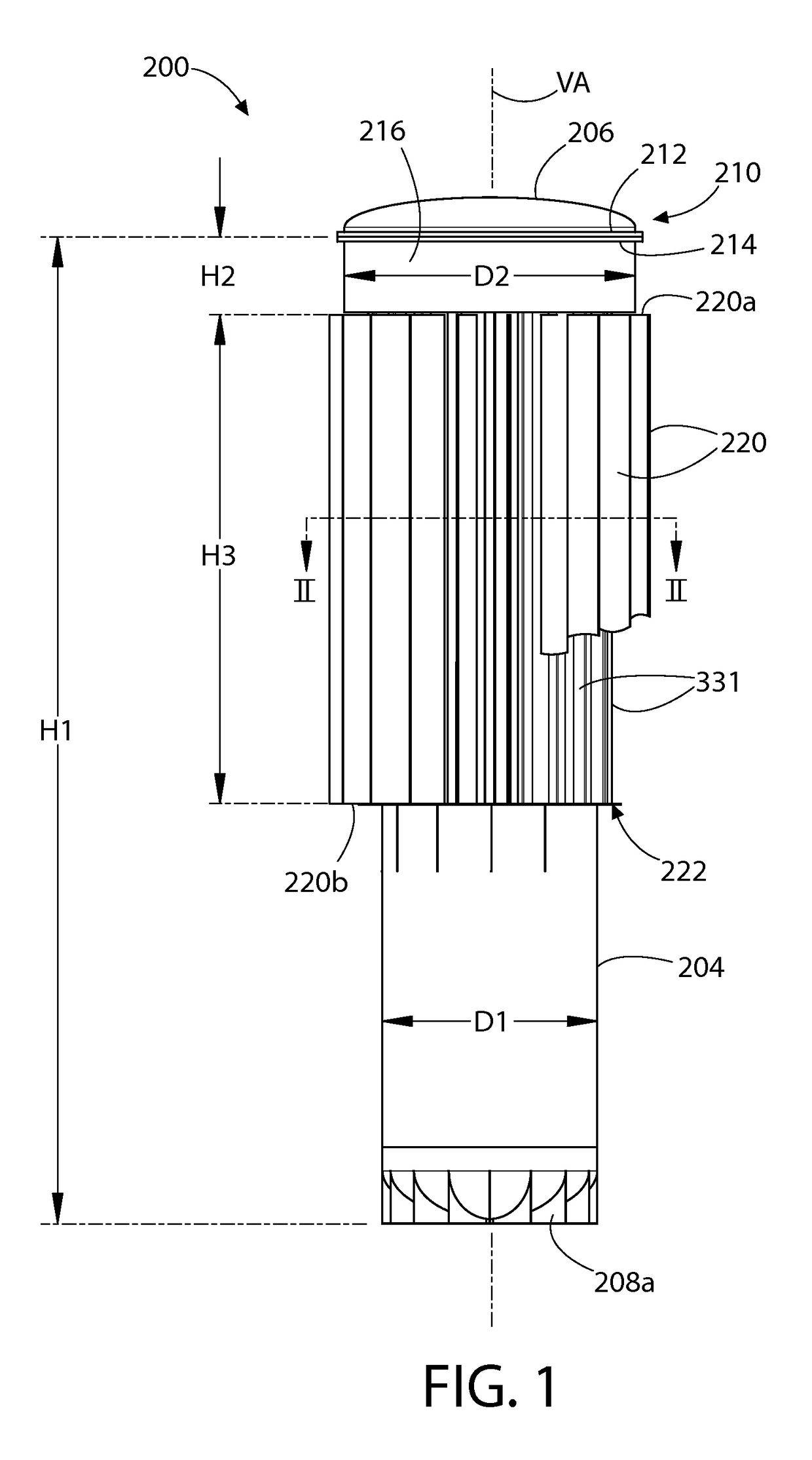
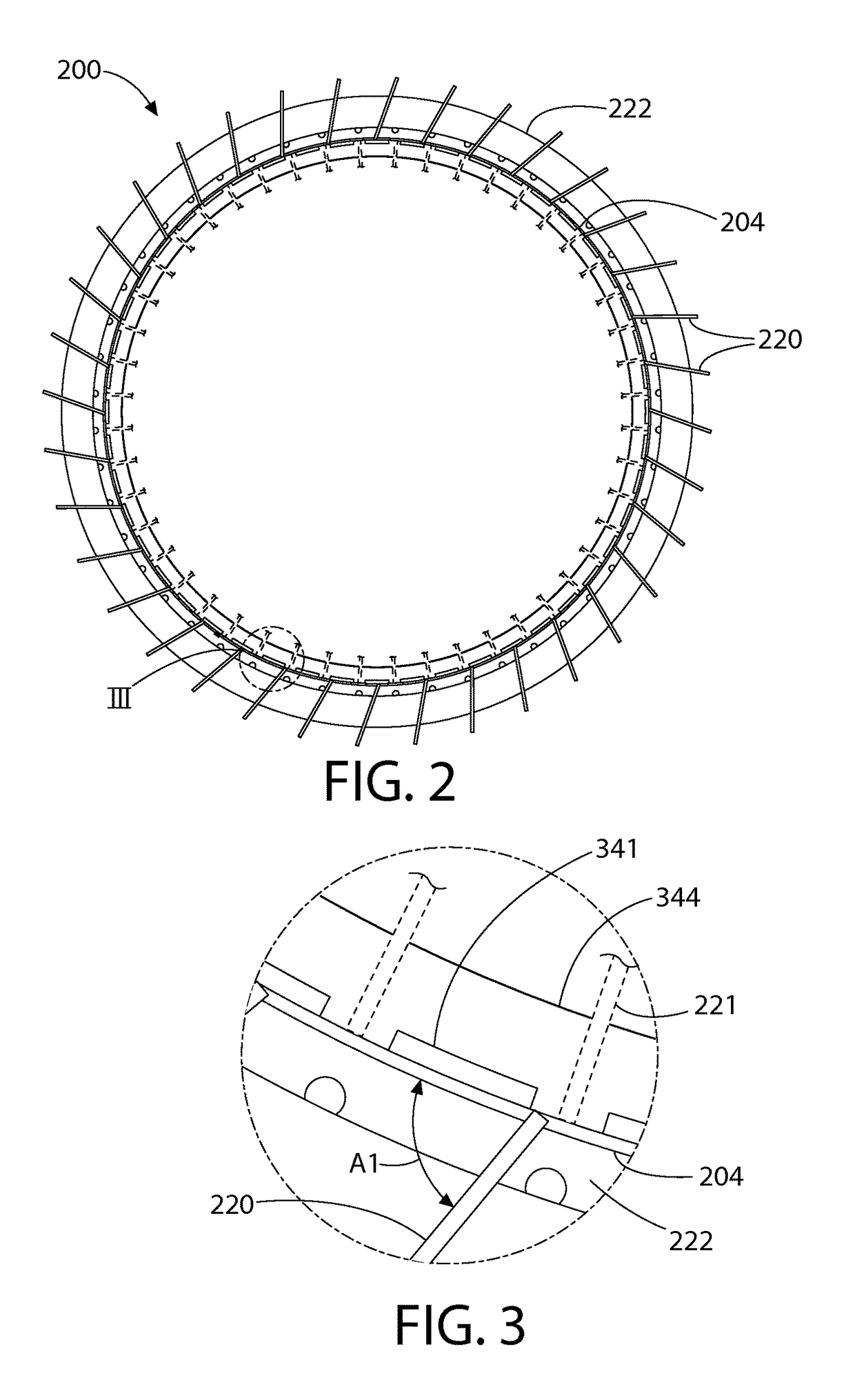
[0019]According to another embodiment, a nuclear reactor containment system includes a containment vessel configured for housing a nuclear reactor, a containment enclosure structure (CES) surrounding the containment vessel, a water filled annulus formed between the containment vessel and containment enclosure structure (CES) for cooling the containment vessel, and a plurality of substantially radial fins protruding, outwards from the containment vessel and located in the annulus. In the event of a thermal enemy release incident inside the containment vessel, heat generated by the containment vessel is transferred to the water filled reservoir in the annulus through direct contact with the external surface of the containment vessel and its fins substantially radial thus cooling the containment vessel. In one embodiment, when a thermal energy release incident occurs inside the containment vessel, and water in the annulus is substantially depleted by evaporation, the air cooling system is operable to draw outside ambient air into the annulus through the air conduits to cool the heat generated in the containment (which decreases exponentially with time by natural convection. The existence of water in the annular region completely surrounding the containment vessel will maintain a consistent temperature distribution in the containment vessel to prevent warping of the containment vessel during the thermal energy release incident or accident.

Problems solved by technology

First, an event that follows a loss-of-coolant accident (LOCA) and involve a rapid large release of thermal energy from the plant's nuclear steam supply system (NSSS) due to a sudden release of reactor's coolant in the containment space.
The reactor coolant, suddenly depressurized, would violently flash resulting in a rapid rise of pressure and temperature in the containment space.
Another second thermal event of potential risk to the integrity of the containment is the scenario wherein all heat rejection paths from the plant's nuclear steam supply system (NSSS) are lost, forcing the reactor into a “scram.” A station black-out is such an event.
Present day containment structures with their monolithic reinforced concrete construction make it extremely difficult and expensive to remove and install a large capital requirement such as a steam generator in the NSSS enclosed by them.
To make a major equipment change out, a hatch opening in the thick concrete dome has to be made at great expense and down time for the reactor.
Unfortunately, far too many steam generators have had to be changed out at numerous reactors in the past 25 years by cutting through the containment dome at billions of dollars in cost to the nuclear power industry.
The heat collected by the component cooling water from plant equipment, however, raises its temperature.
Such a CCW system, however, suffers from several operational problems such as intrusion of debris carried over by the raw cooling water, biological fouling of heat exchanger tubes by raw water, and corrosion of pipes carrying the raw water into the heat exchanger.
Operating nuclear plants often report significant accumulation of sediments and other foulants in the headers of CCW heat exchangers requiring frequent maintenance and degrading thermal performance.
The above weaknesses in the state-of-the-art call for an improved nuclear reactor containment system and component cooling water system.

Method used


Image

  • Component cooling water system for nuclear power plant
  • Component cooling water system for nuclear power plant
  • Component cooling water system for nuclear power plant

Examples


Embodiment Construction

[0053]The features and benefits of the invention are illustrated and described herein by reference to illustrative embodiments. This description of illustrative embodiments is intended to be read in connection with the accompanying drawings, which are to be considered pan of the entire written description. In the description of embodiments disclosed herein, any reference to direction or orientation is merely intended for convenience of description and is not intended in any way to limit, the scope of the present invention. Relative terms such as “lower,”“upper,”“horizontal,”“vertical,”“above,”“below,”“up,”“down,”“top” and “bottom” as well as derivative thereof (e.g., “horizontally,”“downwardly,”“upwardly” etc.) should be construed to refer to the nominal orientation as then described or as shown in the drawing under discussion. These relative terms are for convenience of description only and do not require that the apparatus be constructed or operated in a rigorously specific orient...


PUM


Abstract

A component cooling water system for a nuclear power plant. In one embodiment, the system includes an inner containment vessel housing a nuclear reactor and an outer containment enclosure structure. An annular water reservoir is formed between the containment vessel and containment enclosure structure which provides a heat sink for dissipating thermal energy. A shell-less heat exchanger is provided having an exposed tube bundle immersed in water held within the annular water reservoir. Component cooling water from the plant flows through the tube bundle and is cooled by transferring heat to the annular water reservoir. In one non-limiting embodiment, the tube bundle may be U-shaped.

Description

CROSS-REFERENCE TO RELATED PATENT APPLICATIONS[0001]The present application is a U.S. national stage application under 35 U.S.C. §371 of PCT / US2013 / 056023 filed Aug. 21, 2013, which claims the benefit of U.S. Provisional Patent Application Ser. No. 61 / 691,533 filed Aug. 21, 2012, and is a continuation-in-part of PCT International Patent Application Serial No. PCT / US13 / 42070 filed May 21, 2013, which claims the benefit of U.S. Provisional Patent Application Ser. No. 61 / 649,593 filed May 21, 2012; the entireties of which are all incorporated herein by reference.FIELD OF THE INVENTION[0002]The present invention relates nuclear reactors, and more particularly to a reactor containment system with passive, thermal energy release control.BACKGROUND OF THE INVENTION[0003]The containment for a nuclear reactor is defined as the enclosure that provides environmental isolation to the nuclear steam supply system (NSSS) of the plant in which nuclear fission is harnessed to produce pressurized ste...

Claims


Application Information

Patent Timeline
Patent Type & Authority Patents(United States)
IPC IPC(8): G21C15/18G21C13/02G21C9/012G21D1/04G21C11/08G21C15/26G21C15/12G21C11/02G21C19/07
CPCG21C15/18G21C9/012G21C11/02G21C11/088G21C15/12G21C15/26G21D1/04G21C13/02Y02E30/40G21C19/07Y02E30/30
Inventor SINGH, KRISHNA P.RAJKUMAR, JOSEPH
Owner SMR INVENTEC
Why Eureka
Try Eureka