Device and method for generative component production

a generative component and device technology, applied in the direction of additive manufacturing, manufacturing tools, additive manufacturing, etc., can solve the problems of affecting the quality of generative components, requiring a larger installation space, and requiring shorter auxiliary processing times and installation spaces primarily, and correspondingly poor component quality, and the build-up rate is high

Active Publication Date: 2017-11-28
FRAUNHOFER GESELLSCHAFT ZUR FOERDERUNG DER ANGEWANDTEN FORSCHUNG EV
View PDF21 Cites 4 Cited by
  • Summary
  • Abstract
  • Description
  • Claims
  • Application Information

AI Technical Summary

Benefits of technology

[0016]When using the suggested device for powder-based production methods, such as selective laser melting, the auxiliary processing times can also be reduced considerably. In the case of the previously known principle, the application of a new powder layer takes place by means of a separate powder application device after the exposure of a component layer. During the powder application, no exposure takes place and the beam source is not productive. Using the device suggested here and the associated method, the powder application can take place simultaneously with the exposure, in that the processing head is coupled to the axis for powder coating or the powder coating apparatus. In this case, the processing head follows the axis of the powder application at a fixed distance, so that the powder application takes place simultaneously with the exposure or processing. The auxiliary processing times can thereby be eliminated completely.
[0017]Compared to previous scanner-based systems, the scaling of dimensional size and laser power using the suggested device and the associated method is connected with significantly lower costs for the optical system. For installation space scaling, additional costs are only incurred for correspondingly longer linear axes for moving the processing head. The scaling of the laser power by increasing the number of beam sources can likewise be realised significantly more economically. Whilst in the case of the previous scanner-based concept, the beam quality of single mode lasers is required, in order to achieve the required focus value with the largest possible scanning field (due to the large focal lengths of the focussing lens), the focussing in the suggested device can take place with smaller focal lengths of the lenses, which lends itself to the use of more cost effective diode lasers as beam sources. The scaling of the laser power can take place linearly in units of a diode laser. Additional optical components are not required for the scaling. For certain uses, for example for laser sintering of polymers, surface-emitting semiconductor lasers (VCSEL: Vertical-Cavity Surface-Emitting Lasers) can also be used for realising the intensity distribution or a spot field.
[0024]The method can in principle also be carried out using a device, which guides the laser line formed from the individual laser beams across the processing plane by means of a scanner apparatus—for example formed from movable mirrors. Although this reduces the size of the installation space that can be processed, it has the advantage of increasing the laser power and shortening the build-up process.

Problems solved by technology

However, for a broad industrial use of such a production method, higher build-up rates, shorter auxiliary processing times and larger installation spaces are primarily required.
When increasing the laser power, however, material vaporisation occurs due to the high intensity at the processing location, which results in high splatter and soot formation and also deep-penetration welding, which leads to an unstable process and correspondingly poor component quality.
However, this leads to a reduction of the surface quality and detail resolution.
However, a higher build-up rate can only be achieved using this technology for solid components with significant core volumes.
When using higher laser powers, the high scanning speeds of >2 m / s required therefor also can no longer be achieved constantly, due to the inertia of the scanner mirrors.
This results in a clear thermal shift of the focus position in the size of the Rayleigh length.
However, the scanning field of the scanners used is fundamentally limited by the maximum angle of rotation of the mirrors and also via the focal length of the focussing lens used.
However, this necessitates the development of novel scanning strategies for building up components in a defect-free manner in the overlap region of the individual scanning fields and means a significantly higher cost portion for optical components in larger installation spaces.
This auxiliary processing time scales in conventional selective laser melting with the number of layers and the dimensioning of the installation space in the powder application direction and cannot be used for the exposure.

Method used


Image

  • Device and method for generative component production
  • Device and method for generative component production
  • Device and method for generative component production

Examples


Embodiment Construction

[0010]The object is achieved with the device and the method according to the following description and claims. Advantageous configurations of the device as well as of the method are the subject matter of the dependent patent claims or can be drawn from the following description as well as from the exemplary embodiments.

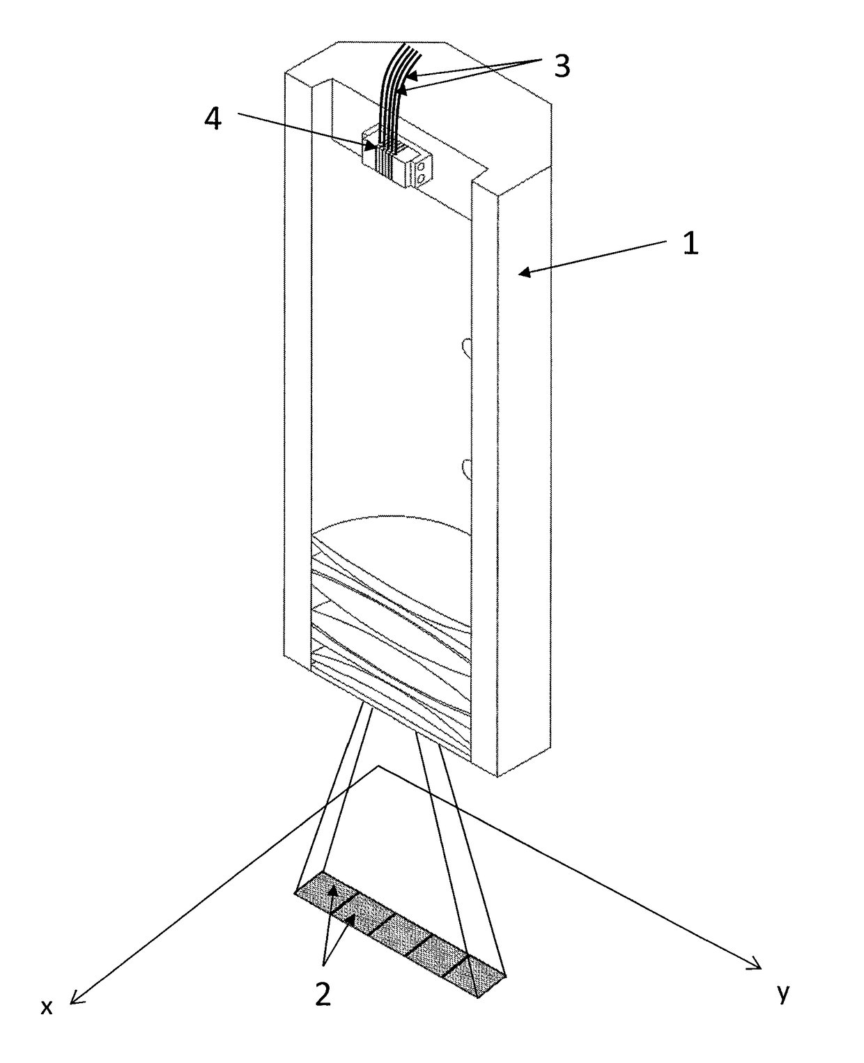
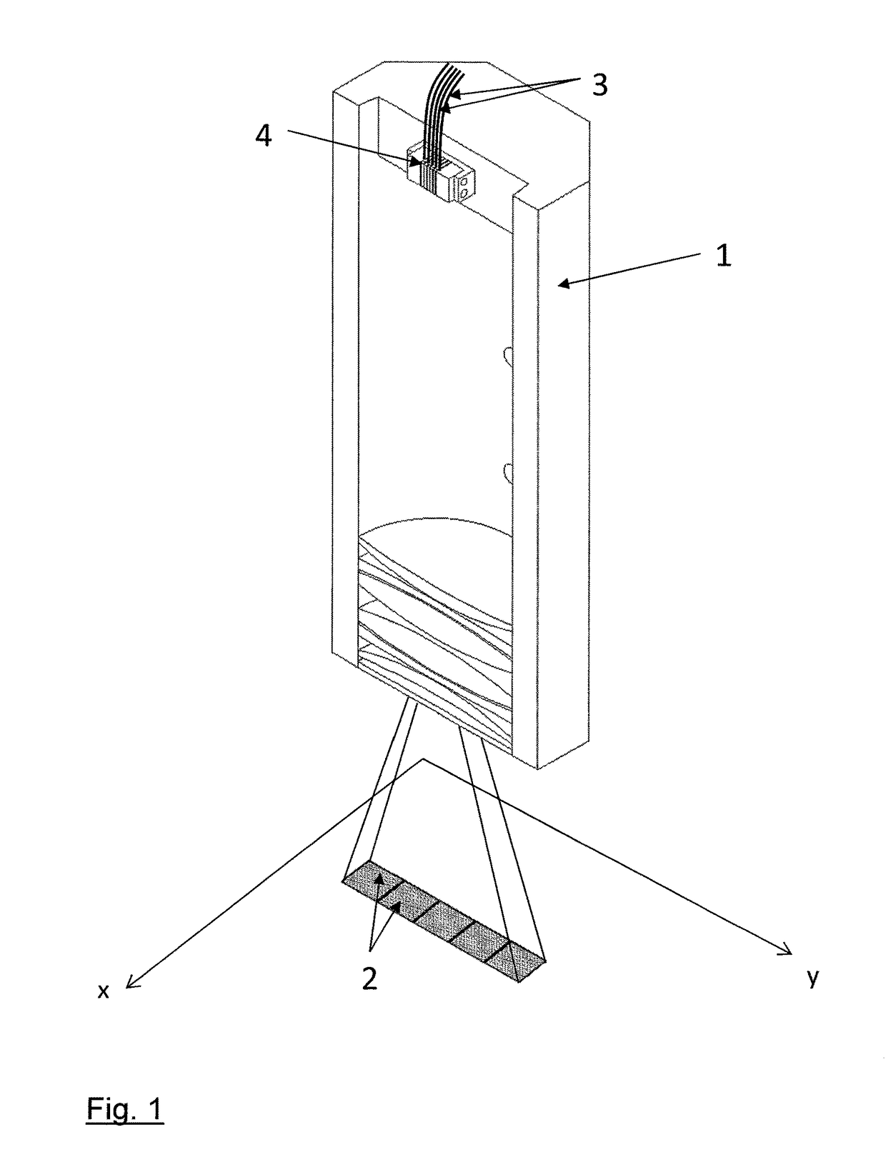
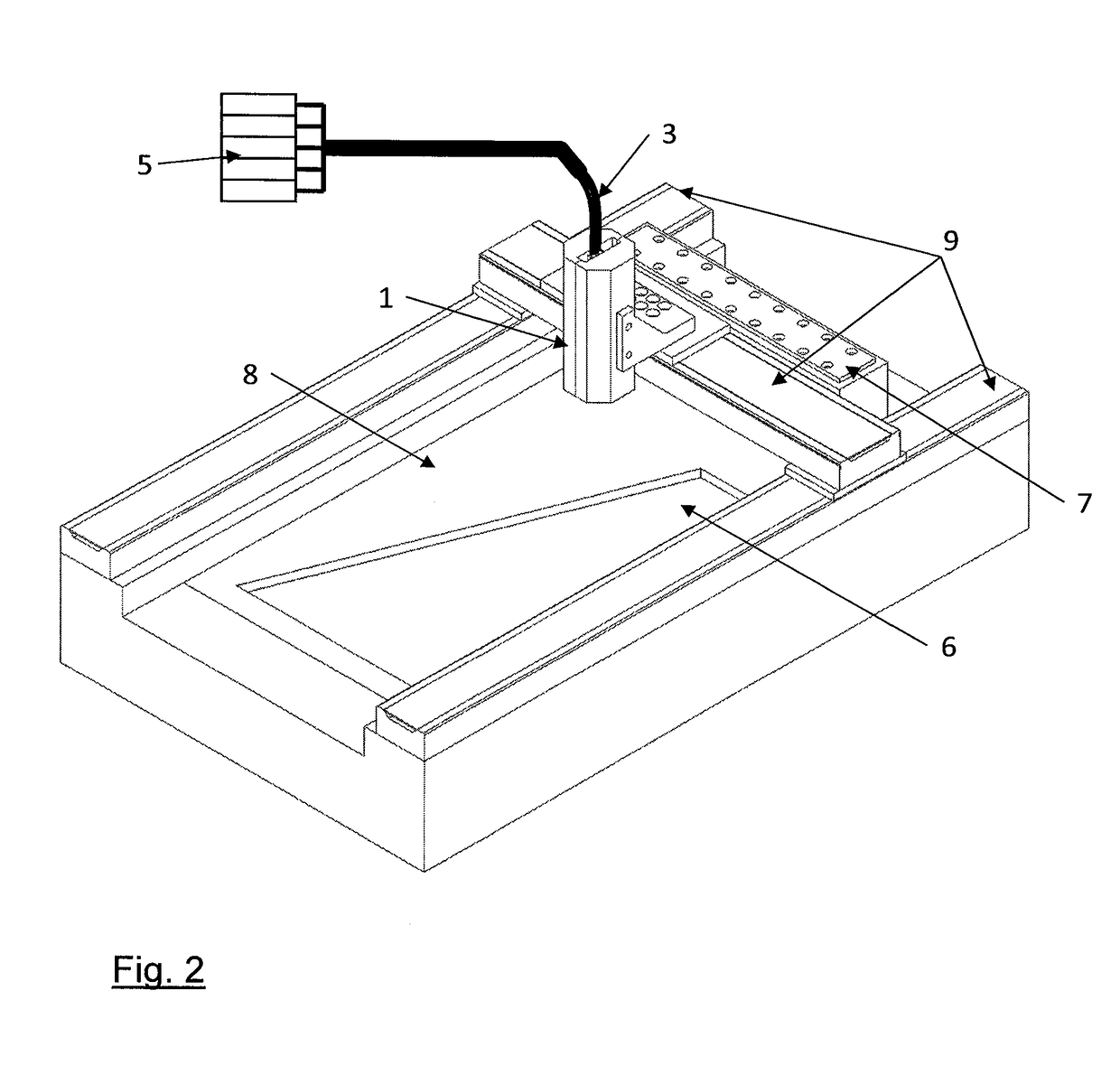
[0011]The suggested device for generative component production has a processing head, using which a plurality of mutually separate laser beams are directed adjacently and / or overlapping to some extent onto the processing plane, in which the workpiece to be processed is provided. The device furthermore comprises a laser beam source arrangement, using which the mutually separate laser beams can be generated, a movement apparatus, which can generate a relative movement between processing head and processing plane in mutually parallel planes, particularly by moving the processing head across the processing plane, an apparatus for providing the material for the component i...


PUM

PropertyMeasurementUnit
d50 particle sizeaaaaaaaaaa
sizesaaaaaaaaaa
poweraaaaaaaaaa

Abstract

The present invention relates to a device for laser-based generative component production. The device comprises a processing head (1), using which a plurality of mutually separate laser beams are directed adjacently and / or overlapping to some extent onto the processing plane, The processing head (1) is moved across the processing plane using a movement apparatus (9), while the mutually separate laser beams are modulated independently of one another in terms of intensity, in order to obtain the desired exposure geometry. The laser power and the dimensional size can be scaled cost effectively during the generative production using the suggested device and the associated method.

Description

CROSS-REFERENCE TO RELATED APPLICATION[0001]This is a §371 application of International patent application number PCT / EP2014 / 001879 filed Jul. 9, 2014, which claims the benefit of German patent application number 10 2013 011 676.7 filed on Jul. 11, 2013, and which is incorporated herein by reference.TECHNICAL FIELD OF APPLICATION[0002]The present invention relates to a device and a method for laser-based generative component production.[0003]One example for a laser-based generative production method is selective laser melting (SLM), using which functional components can be produced in layers. Selective laser melting and similar generative production methods offer the possibility to produce components with complex (internal) geometries, which cannot be produced using conventional production methods, such as for example machining or casting methods.[0004]During selective laser melting, the component is divided into layers (typ. <100 μm) starting from a 3D CAD model by means of spec...

Claims


Application Information

Patent Timeline
Patent Type & Authority Patents(United States)
IPC IPC(8): B23K26/08B23K26/354B23K26/06B23K26/00B29C67/00B23K26/342B22F3/105
CPCB23K26/0876B22F3/1055B23K26/0081B23K26/0608B23K26/342B29C64/20B29C64/153B23K26/354B22F2003/1056B22F2003/1057Y02P10/295B29C64/268B29C64/277Y02P10/25B22F10/28B22F10/36B22F10/322B22F12/47B22F12/44B22F12/45
Inventor EIBL, FLORIANHAGEDORN, YVES-CHRISTIANJAUER, LUCASMEINERS, WILHELM
Owner FRAUNHOFER GESELLSCHAFT ZUR FOERDERUNG DER ANGEWANDTEN FORSCHUNG EV
Why Eureka
Try Eureka