
Apparatus and method for improving detection precision in laser vibrometric studies

a technology of vibrometric studies and instruments, applied in the field of measurement, can solve the problems of affecting the detection accuracy of laser vibrometric studies, so as to improve the accuracy of collecting data and improve the accuracy of vibratory characteristic data

Active Publication Date: 2017-11-28
UNITED STATES OF AMERICA THE AS REPRESENTED BY THE SEC OF THE ARMY
View PDF11 Cites 2 Cited by
  • Summary
  • Abstract
  • Description
  • Claims
  • Application Information

AI Technical Summary

Benefits of technology

The invention is a laser vibrometer that improves the accuracy of vibtaomy data collected from an object. It uses multiple channels of light beams to transmit and collect light in a way that ensures there is no overlap between them in time. This allows for more accurate data collection from the moving object. The method involves interrogating the object sequentially with each channel of light and collecting the backscattered light from it. The collected light is then converted to electrical currents and aggregated to improve the accuracy of the data collected. Overall, this technology provides improved accuracy and efficiency in obtaining vibration data from objects.

Problems solved by technology

However, the requirement of direct physical contact between the tires and the sensor wires and cables impedes covert deployment of the sensing technology.
Furthermore, it is a technical hurdle to differentiate between different vehicles using the piezo-electric sensor wires and cables since larger trucks can have more than two sets of tires.
As such, it can be quite difficult to differentiate between a large truck with four sets of tires or two successively passing small cars with two sets of tires each or even two bicycles traveling side by side.
However, the presence of optical speckles in the light beams back scattered from the passing vehicle diminishes their effectiveness.
The optical speckles result from the non-mirror like finishes of a typical vehicle.
Even more challenging is that because vehicles are moving with non-zero speed, both the variation in surface interrogation locations and the very likely presence of wind flow will lead to rapid and random changes in the speckle patterns being collected by the conventional laser vibrometers.
Such random and rapidly changing optical speckles cause the conventional laser vibrometers to produce sudden “drop-offs” in readout signals as the conventional laser vibrometers cannot respond as fast as the time varying optical speckles.
The drop-offs in output signals render the conventional laser vibrometer un-reliable in monitoring the vibratory signatures of moving vehicles as the output signals are punctuated with un-predictable and erroneous sections of readouts.
Defective packaging leads to products that could be unsafe for consumption or could result in legal and financial liabilities.
For example, defective packaging could render medical vaccines hazardous for human application due to the presence of bacterial contamination.
Current approaches to product integrity assurance cannot be applied on the assembly line as packages are being prepared and produced.
These approaches are time-consuming and unfit for online real time testing of the packages during the manufacturing process.
Further hindering the application of these submerging tests are the costs associated with the off-line laboratories.
If the packages under test are found to be defective, the whole lot of finished packages and goods are assumed to be defective as well and most likely will need to be repackaged or destroyed, thus leading to further economic inefficiencies.
However, these approaches are technically limited due to the relatively long wavelengths of microwaves.
Beams of microwaves cannot be focused as tightly in space as other beams such as from a laser.
Such an extensive microwave beam profile will result in confusion in physiological signatures readout in crowded areas where the spacing between two different persons can be comparable to or even shorter than the wavelength of the microwave beams.
In such crowded space, the prior art microwave-based technologies will produce readings that are weight-averaged among the many different people simultaneously being illuminated by the microwave beam, hence leading to erroneous readouts and assessments.
Another challenge facing the prior-art microwave solutions is that the surface agitation of a person due to his or her heartbeat can be very small in amplitude (i.e. smaller than 0.1 micrometer).
Such a length scale is far smaller than the wavelength of the microwave beam and it is technically difficult for microwave based technologies to detect such minute signatures.
Gun barrels undergo extreme pressure and heat conditions when firing projectiles.
Excessive firing frequency and / or extended rounds of firing causes the barrels to exhibit fatigue cracks that threaten the integrity of the barrel.
Upon growth to certain extent, the fatigue cracks can cause the barrel to disintegrate and compromise the safety of the operating personnel and / or carrier platform of the gun assembly such as a fighter aircraft.
However, these techniques involve off-line testing via removal of the barrels from the gun assembly which is time consuming, costly and sometimes impractical.
Visual inspection, either manually or via machine vision is time consuming and highly subjective.
Furthermore, subsurface fatigue cracks might not exhibit any signs on the surface of the barrel.
Hence, visual inspection techniques are unable to produce reliable and accurate assessment on the condition of the gun barrels in a timely manner.
Unfortunately, gun barrels in general are of a cylindrical shape with circular surfaces.
The relatively small radii of curvature of gun barrels poses severe challenges in ensuring good physical contact between the barrel and the ultrasonic transducers.
The lack of good physical contact between the ultrasonic transducer and the gun barrel surface under test leads to reduced transmission of interrogating ultrasounds and the associated echoes beings scattered back from fatigue cracks, resulting in reduced signal to noise ratio and unreliable assessments on the presence and location of fatigue cracks.

Method used


Image

  • Apparatus and method for improving detection precision in laser vibrometric studies
  • Apparatus and method for improving detection precision in laser vibrometric studies
  • Apparatus and method for improving detection precision in laser vibrometric studies

Examples


Embodiment Construction

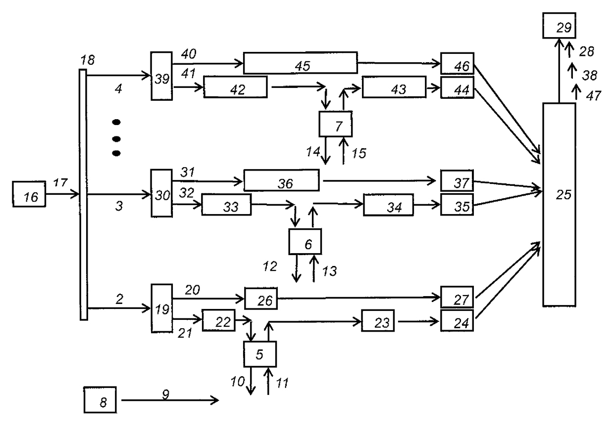
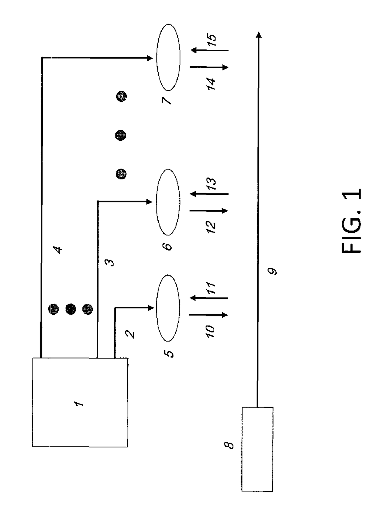
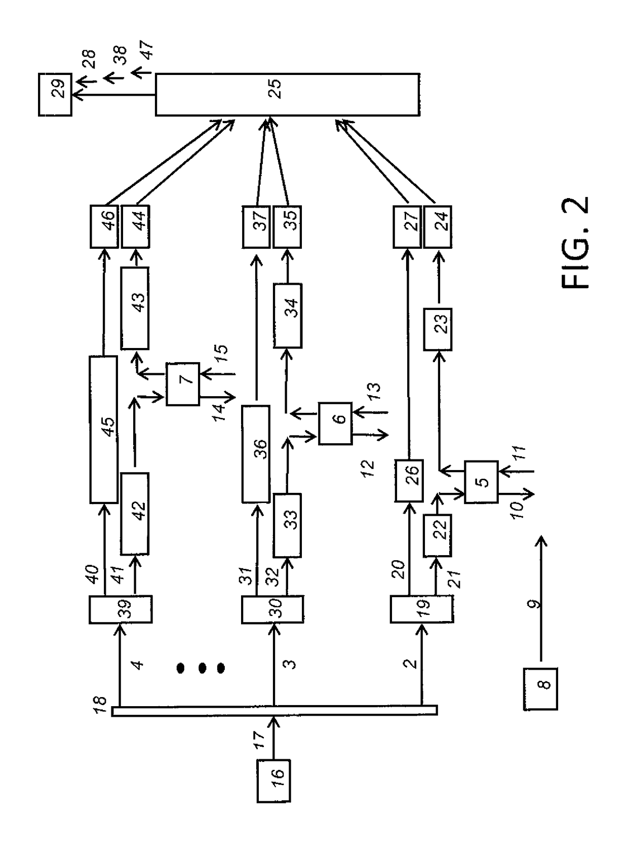
[0031]The present invention relates to the detection and measurement of the vibratory characteristics of an object, in particular the vibratory characteristics of a moving object. A laser vibrometer comprises multiple channels of light beam transmission and collection resulting in a higher signal to noise ratio for the collected data. Each of the multiple channels are temporally different, sequential and non-overlapping. Further, the channels are spatially located in relation to the application they are employed in to maximize the coverage of the vibrometer.

[0032]Due to the improved signal to noise ratio (SNR) and speckle tolerant operation, the laser vibrometer is particularly suited to accurately determine the vibratory characteristics of moving objects. When conducting remote and non-contact measurements on objects moving relative to the observation base and / or instrumentation, only finite time periods of observation are available to the instrument and observer. These finite and ...


PUM


Abstract

A laser vibrometer for measuring the vibratory characteristics of an object and more specifically, a moving object, has an improved signal to noise ratio due to multiple channels. A laser is split into a plurality of channels and then for each channel split again into a reference beam and a probe beam. The probe beam is directed at the object and the back scattered reflections are collected and compared to the reference beam to determine the vibratory characteristics of the object. The received signals from the multiple channels are different, sequential and non-overlapping.

Description

FEDERAL RESEARCH STATEMENT[0001]The invention described herein may be manufactured, used, and licensed by or for the U.S. Government for U.S. Government purposes.CROSS REFERENCE TO RELATED APPLICATION[0002]The present application is a non-provisional application of U.S. provisional application Ser. 62 / 052,579, filed Sep. 19, 2014, the contents of which are incorporated herein by reference.BACKGROUND OF INVENTIONField of the Invention[0003]The present invention relates to measurement, and more particularly to the measurement of vibratory characteristics of an object.Related Art[0004]Vibrometer technology involves the detection and analysis of pressure waves, such as acoustic waves or water waves that might bear information regarding agitation sources of interest to the observer. Laser vibrometers utilize a beam of light, such as a laser, which is split into two parts. One forms a reference beam and the second forms a sensing beam which impacts the target surface, e.g., the pressure-s...

Claims


Application Information

Patent Timeline
Patent Type & Authority Patents(United States)
IPC IPC(8): G01H9/00
CPCG01H9/00
Inventor SWAMINATHAN, VENKATARAMANTRIVEDI, SUDHIR B.WANG, CHENCHIAJIN, FENG
Owner UNITED STATES OF AMERICA THE AS REPRESENTED BY THE SEC OF THE ARMY
Learn More